A flange can also be a plate or ring to form
a rim at the end of a pipe when fastened to the pipe. A blind flange is a plate
for covering or closing the end of a pipe. A flange joint is a connection of
pipes, where the connecting pieces have flanges by which the parts are bolted
together.
Although the word flange generally refers to
the actual raised rim or lip of a fitting, many flanged plumbing fittings are
themselves known as 'flanges':
There are many
different flange standards to be found worldwide. To allow easy functionality
and interchangeability, these are designed to have standardised dimensions.
Common world standards include ASA/ASME (USA), PN/DIN (European), BS10
(British/Australian), and JIS/KS (Japanese/Korean). In the USA, ANSI stopped
publishing B16.5 in 1996, and the standard is ASME B16.5
Stainless Steel Flange,Machining Stainless Steel Flange, Stainless Steel Pipe Fitting Flange,Galvanized Stainless Steel Flange Yixing Steel Pole International Trading Co., Ltd , https://www.yx-steelpole.com
**Introduction**
In portable electronic devices, there is a growing demand for batteries that offer high capacity, compact size, and low weight. Lithium batteries have largely replaced nickel-cadmium and nickel-hydrogen batteries in both primary and secondary battery applications. However, one major drawback of lithium batteries is their poor tolerance to overcharging and overdischarging. To prevent damage, a protection circuit board is typically integrated into the battery system. This protection board is powered by the lithium battery itself, and under normal conditions, it draws a leakage current of about 2μA to 3μA. If this leakage current exceeds 5μA, it can significantly reduce the battery’s storage life, and in severe cases, cause permanent damage. Therefore, there is an urgent need for a reliable tester to measure and monitor the leakage current of lithium battery protection boards.
This study presents a rapid leakage current detector for lithium battery protection boards, designed using the ICL7107 integrated circuit. The device is capable of accurately measuring and alerting users when the leakage current exceeds safe limits, ensuring the longevity and safety of the battery system.
**1. Hazard Analysis of Excessive Leakage Current in the Protection Circuit**
**1.1. Analysis of the Protection Circuit**
The schematic diagram of the lithium battery protection circuit is shown in Figure 1. In this design, U1 is a Ricoh R5421N151F lithium battery protection chip, and U2 is a Sanyo FTD2017 metal-oxide semiconductor transistor (MOST). When abnormal conditions such as overcharge, overdischarge, overcurrent, or short circuits occur, the MOST acts as a switching component to quickly disconnect the circuit, thereby protecting the battery from damage.
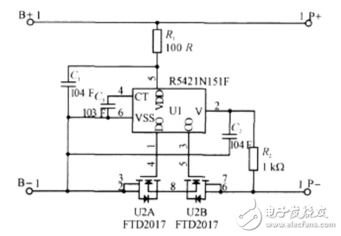
*Figure 1: Schematic diagram of the lithium battery protection circuit*
**1.2. Sources of Leakage Current**
As illustrated in Figure 1, the leakage current in the protection circuit can originate from three main sources: 1) leakage through capacitor C1, 2) internal working current of the R5421N151F chip, and 3) leakage from the FTD2017 MOSFET. Any abnormality in these components—such as excessive leakage from C1, malfunctioning internal current in the chip, electrostatic breakdown of the FTD2017, or copper foil shorting on the PCB—can lead to a significant increase in leakage current.
**1.3. Hazards of Excessive Leakage Current**
As shown in Figure 1, the protection board is connected across the battery terminals. If the leakage current becomes too high, it not only reduces the effectiveness of the protection mechanism but also shortens the battery's lifespan. In extreme cases, the battery may be permanently damaged. According to industry data, about 3‰ of protection boards suffer from excessive leakage current. Due to its hidden nature, this issue often goes undetected for 3 to 6 months before causing serious problems. For example, if a lithium battery costs 20 yuan per unit and a manufacturer produces 10,000 units daily, a daily loss of 600 yuan due to faulty protection boards could result in an annual loss of 200,000 yuan, along with reputational damage.
**2. Principle of Protection Board Leakage Current Testing**
**2.1. Tester Working Principle**
The tester consists of several key components: a reference voltage circuit, a test voltage supply, a comparison circuit, a digital display or microampere meter, and an alarm system. Its schematic is shown in Figure 2.
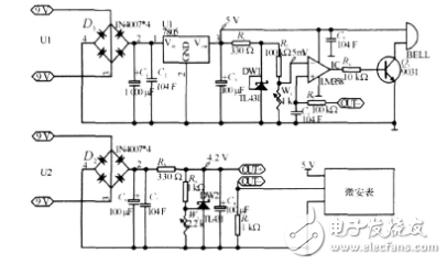
*Figure 2: Schematic diagram of the protection board leakage current tester*
**Reference Circuit:**
R1 and DW1 form a stable 2.5V low-temperature reference voltage source. This is divided by R2 and W1 to produce a reference voltage of approximately 5mV, which is then applied to the inverting input of the LM358 comparator.
**Test Voltage Circuit:**
The tester is designed to operate at the typical lithium battery voltage of 4.2V. After regulation by DW2, the voltage is adjusted via W2 to provide the appropriate test voltage for the protection board.
**Leakage Current Measurement:**
The test voltage is applied across the protection board through the OUT+ and OUT- sockets and test leads. The leakage current passing through the protection board causes a voltage drop across resistor R7, calculated as:
UR7 = ILeak × R7 = XμA × 1kΩ = XmV (assuming leakage current is X μA).
This voltage drop is filtered by R3 and C4, and then fed into the non-inverting input of the LM358. When compared to the 5mV reference voltage, if the voltage from the leakage current exceeds 5mV, the output of the LM358 becomes high, triggering the 9013 transistor and activating the buzzer to generate an audible alarm. This real-time feedback helps identify and isolate faulty protection boards efficiently.
September 25, 2025