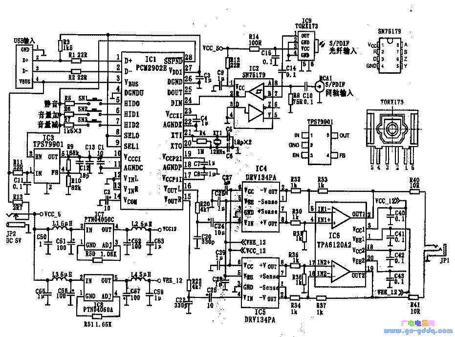
Although the output power of a headphone amplifier may not be very high, achieving good performance under amateur conditions can be challenging. To reach the desired level, many headphone amplifiers use discrete components, as the low power output makes class A amplification relatively common. Under such conditions, it's not easy to achieve optimal results. The headphone amplifier described here uses a specialized integrated circuit from Texas Instruments (TI), making it suitable for DIY projects under amateur conditions while offering preliminary professional quality. First, Main Features The main features of this headphone amplifier include: Second, Circuit Principle and ICs Besides the S/PDIF receiving circuit, this design is composed of integrated circuits from Texas Instruments, including the input and DAC circuit, unbalanced-balanced line amplifier, balanced input mode power output stage, and power supply circuit. Some parts of the digital signal reception are handled by other components, such as the TROX173 from Toshiba for optical signals and SN75179 for coaxial S/PDIF signals. Most of the other functions, like decoding and encoding, are managed by TI’s PCM2902, which includes USB input, analog input, S/PDIF digital codec, ADC, DAC, and analog filter. A total of nine integrated circuits are used in the system, and the general schematic is shown in the figure below. 1. Input and DAC Circuit The input and DAC circuits are composed of PCM2902, TORX173, and SN75179. Their characteristics and functions are as follows: This circuit only uses the USB and S/PDIF input modes of PCM2902, and the analog input is not used. 2. Unbalanced Balanced Line Amplifier The DRV134, used in the rear-end headphone amplifier TPA6120A2, operates in a balanced input mode. To match the front-end output, the circuit uses TI’s Burr-Brown balanced audio line amplifier DRV134, which has an unbalanced input and balanced output. It integrates resistors needed for gain setting and avoids issues with channel imbalance caused by improper selection of external components. The gain is fixed at 6dB. 3. Balanced Input Mode Power Output Stage TPA6120A4 TPA6120A4 is a current feedback high-fidelity headphone amplifier with wide power supply voltage range, low distortion, high slew rate, and excellent noise performance. It offers high stability, wide frequency response, and strong crosstalk suppression. Its technical specifications include THD+N of 0.00014%, DNR and SNR of 120dB, and a slew rate of 1300V/μs. 4. Power Circuit PTN4050A and PTN4050C To provide dual power supplies for the DRV134 and TPA6120A2, a DC-DC power supply circuit is added, converting +5V to ±12.5V. This circuit uses modular DC-DC converters PTN4050A and PTN4050C, which have simpler peripheral circuits compared to traditional three-terminal regulators and require only one resistor to set the output voltage. Third, Assembly and Adjustment The main ICs in this circuit are in flat patch packages, making them less convenient for breadboard use. However, with proper soldering techniques, they can still be assembled. If possible, using a PCB simplifies the process. Key considerations during assembly include decoupling capacitors, component selection, and ensuring stable power supply connections. Fourth, Final Testing After assembling all components, check for any installation errors. Begin by testing the power supply before connecting the load. Use a multimeter to measure voltages and ensure everything is functioning correctly. Once confirmed, connect the headphones and test the audio playback through USB or S/PDIF inputs. Finally, enjoy your DIY headphone amplifier and compare its sound quality with other sources like your computer's built-in sound card or an external S/PDIF device if available. Usb3.1 5Gbps Data Cable,Usb3.1 Type-C Data Cable,Usb-C 3 Data Cable,Data Cable With Braided Cover Dongguan Pinji Electronic Technology Limited , https://www.iquaxusb4cable.com
