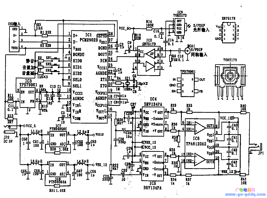
Although the output power of a headphone amplifier isn't very high, achieving good performance under amateur conditions is no easy task. To reach a satisfactory level, many headphone amplifiers use discrete components. Since the output power isn't large, a class A amplifier isn't uncommon. However, under such conditions, it's challenging to get everything right. The headphone amplifier described here uses a specialized integrated circuit produced by Texas Instruments (TI). It’s suitable for DIY projects in amateur settings and offers a level of professional quality. 1. Main Features The main features of this headphone amplifier include: 2. Circuit Principle and ICs In addition to the S/PDIF receiving circuit, this design uses integrated circuits from TI, including the input and its DAC circuit, unbalanced balanced line amplifier, balanced input mode power output stage, and power supply circuit. Part of the digital signal reception for S/PDIF in optical mode is handled by the Toshiba TROX173, while the coaxial mode is managed by the SN75179. Most other functions are performed by the PCM2902, which includes USB input, analog input, codec for S/PDIF digital signals, ADC, DAC, and analog filter. A total of nine integrated circuits are used in the system. The general schematic is shown below. 3. Input and DAC Circuit The input and DAC circuits consist of the PCM2902, TROX173, and SN75179. Their characteristics and functions are as follows: This circuit only uses the USB and S/PDIF input modes of PCM2902, and the analog input is not used. 4. Unbalanced Balanced Line Amplifier The DRV134 is used to match the unbalanced output of PCM2902 with the balanced input of the TPA6120A2. This device is an unbalanced input, balanced output line amplifier that integrates resistors needed to set the gain, ensuring channel balance without worrying about component selection. It has a fixed gain of 6dB, is available in an 8-pin package, and has internal equivalent circuitry. 5. Balanced Input Mode Power Output Stage TPA6120A4 TPA6120A4 is a current feedback high-fidelity headphone amplifier with the following main features: The current feedback amplifier offers significant advantages, such as a high slew rate that prevents odd harmonic distortion, stable transient response, and wide frequency range with low noise and distortion. 6. Power Circuit PTN4050A and PTN4050C Both DRV134 and TPA6021A2 require dual power supplies. To use the USB bus +5V power, a DC-DC power supply circuit providing +5 to ±12.5V is added. This circuit uses modular DC-DC converters PTN4050A and PTN4050C, offering simplified peripheral applications compared to traditional three-terminal regulators. 7. Assembly and Adjustment The main ICs are in flat patch packages, making them less convenient for breadboard use. However, they have fewer pins and manageable pitch, so skilled soldering techniques are sufficient. If possible, using a PCB makes the process easier. 8. Final Testing After installation, check for any connection errors. Start by powering the power supply and checking for normal operation. Ensure the output voltages are correct and the load adaptability is good. Use a multimeter to measure the output of the TPA6120A2 for any DC voltage to ground. Connect headphones and test the audio source. Finally, connect the USB or S/PDIF and enjoy the sound. Pd Fast Charging For Type-C,Colorful Usb4 Data Cable,Pd Charger Type-C Data Line,Usb C To Type-C Pd Charger Cable Dongguan Pinji Electronic Technology Limited , https://www.iquaxusb4cable.com
