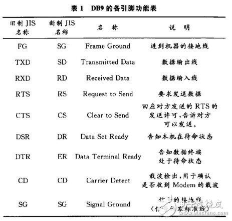
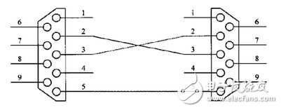
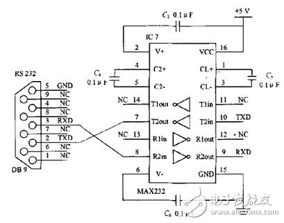
With the rapid development of information technology and scientific and technological progress, in many modern centralized management systems, it is necessary to perform statistics, analysis, printing, alarming, etc. on the field data, and at the same time, real-time control of field devices is required to complete various operations. As an indispensable part of the control system, single-chip microcomputer has been widely used in various fields. Because the single-chip microcomputer has the characteristics of small size, low price and strong adaptability, generally in the industrial control system, the collection of various data and the control of the actuator are all completed by the single-chip microcomputer. The computing power of single-chip microcomputers is limited, making it difficult to perform complex data processing. In the more complex automatic control system, the industrial computer is usually the upper computer, the single chip is the lower computer, the data acquisition and the device control are completed by the single chip microcomputer, and the complex computer completes various complicated data processing and the single chip microcomputer. control. In the distributed control system, most of the MCUs are used as the lower computer for data acquisition and field control. In these applications, the MCU only directly faces the bottom of the controlled object, and further analyzes and processes the collected data. It is done by a powerful PC. Therefore, there is a large amount of data exchange between the PC and the microcontroller. In the standard configuration of most PCs, there is one to multiple RS 232 serial ports, because the RS 232 serial port is responsible for a large amount of data exchange between the PC and the microcontroller. The single-chip microcomputer 89C52 is used for automatic control and data transmission, and performs data communication to the upper computer through the RS 232 interface. 1 RS 232 serial communication 1.1 RS 232C standard The full name of the RS 232C standard (protocol) is the EIA-RS-232C standard, in which EIA (Electronic Industry AssociaTIon) represents the American Electronics Industry Association, RS (ecommeded standard) represents the recommended standard, 232 is the identification number, and C represents the latest RS 232. modify. Prior to this, there were RS 232B, RS 232A, which specified the connection cable and mechanical, electrical characteristics, signal functions and transmission process. 1.2 RS 232 interface pin definition Since the RS 232C does not define the physical characteristics of the connector, various types of connectors of DB-25, DB-15 and DB-9 have appeared, and their pin definitions are also different. The commonly used connector interface diagram is shown in Figure 1. The pin functions of DB9 are shown in Table 1. Figure 1 DB9 pin diagram The RS 232C standard interface has 25 lines, which are 4 data lines, 11 control lines, 3 timing lines, 7 spare and undefined lines, and only 9 are commonly used. They are: (1) Status line Data Set Ready (DSR): A valid (ON) state indicating that the data communication device is available. Data Terminal Ready (DTR): A valid (ON) state indicating that the data terminal equipment is available. These two signals are sometimes connected to the power supply and are immediately active when powered up. The two device status signals are valid, only indicating that the device itself is available, and does not indicate that the communication link can start communication. Whether or not communication can be started is determined by the following control signals. (2) Contact line Request to Send (RTS): The DTE is ready to send data to the DCE. The DTE makes the signal valid (ON state) and informs the DCE to send data to the DCE. Clear to Send (CTS): A response signal to the RTS. When the DCE is ready to receive data from the DTE, the signal is asserted and the DTE is notified to begin transmitting data. The RTS/CTS request response contact signal is used for switching between the transmission mode and the reception mode in the half-duplex MODEM system. In a full-duplex system, because the bidirectional channel is configured, the RTS/CTS contact signal is not required to make it high. (3) Data line Transmitted Data (TXD): The DTE sends data to the DCE. Received Data (RXD): The DCE sends data to the DTE. (4) Ground wire There are two lines SG, PG: signal ground and protective ground signal line. (5) the rest Carrier DetecTIon (CD): Used to indicate that the DCE has been connected to the communication link, informing the DTE that it is ready to receive data. Ringing indication (Ringlng, RI): When the DCE receives the ringing call signal sent by the switching station, it makes the signal valid (ON state), notifies the DTE that it has been called. In a typical application system, information is often transferred between the CPU and the I/O device. Both are DTE, the communication between the host computer and the single-chip microcomputer 89C52, both sides can send and receive, and their connection only needs to use three. The line can be, that is, RXD, TXD and GND. This connection mode, that is, when two serial ports are connected, the receiving data pins are connected with the transmitting data pins, and cross each other, and the signal ground corresponding to the ground. The connection method is shown in Figure 2. Figure 2 Serial port connection diagram between the host computer and the microcontroller 1.3 Concept of baud rate In serial communication, the data bits transmitted per second are called the baud rate. If the data transmission rate is 1200 baud, use N. In the 8.1 frame format (10 bits), the number of bytes transmitted per second is 120, and the transmission time of each bit in the byte is the reciprocal of the baud rate: T=1/1 200=0.833 ms. Similarly, if the baud rate of data transfer is 1 9 200 baud, then each bit in the byte is transmitted T = 1/19 200 = 0.052 ms. According to the baud rate of data transfer, that is, the transfer time of each bit in the byte, the normal I/O port can be used to simulate the timing of serial communication. 1.4 Electrical Characteristics of RS 232C (1) Logic level On TXD and RXD: Logic 1 (MARK): -3 to -15 V; Logic 0: +3 to +15 V. On the control lines of RTS, CTS, DSR, DTR and DCD: The signal is valid (on, ON state, positive voltage): +3 ~ +15 V; Invalid signal (open, OFF state, negative voltage): -3 to -15 V. It can be seen from the above definition that the level of signal inefficiency is lower than -3 V, that is, when the absolute value of the transmission level is greater than 3 V, the circuit can be effectively checked out, between -3 and +3 V. The voltage is meaningless. Voltages below -1 5 V or above +15 V are also considered meaningless. Therefore, in actual operation, the absolute value of the level should be between 3 and 15 V. When the computer communicates with the TTL level device, the RS 232/TTL level conversion device is required when the above computer communicates with the MCU. The MAX232 is commonly used. 1.5 RS 232 and the interface circuit between the microcontroller MAX232 Since the level of the RS 232 signal does not match the level of the serial port signal of the microcontroller, level shifting between the two must be performed. The MAX232 is powered by a single +5 V supply. It can be level-shifted with only five high-precision 10μF/50 V tantalum capacitors. The converted serial signal TXD and RXD are directly connected to the serial port of the host computer. The internal structure of the MAX232 chip can be basically divided into three parts: The first part is the charge pump circuit. It consists of 1, 2, 3, 4, 5, 6 feet and 4 capacitors. The function is to generate two power supplies of +12 V and -1 2 V, which are required for the RS 232 serial port level. The second part is the data conversion channel. The two data channels are formed by the 7, 8, 9, 10, 11, 12, 13, and 14 legs. Among them, 13 pins (R1in), 12 pins (R1out), 11 pins (T1in), and 14 pins (T1out) are the first data channels. 8 feet (R2in), 9 feet (R2out), 10 feet (T2in), and 7 feet (T2out) are the second data channels. TTL/COMS data is converted from T1in, T2in input to RS 232 data from T1out, T2out to computer DB9 plug; DB9 plug RS 232 data is converted from R1in, R2in input to TTL/COMS data and output from R1out, R2out. The third part is power supply. 1 5 pin GND, 16 pin VCC (+5 V). Figure 3 Connection diagram of RS 232 and MAX232 1.6 Inadequacies of RS 232 (1) The transmission distance is limited, and the actual maximum transmission distance is only 50 m. (2) The transmission rate is low, and the maximum rate is 19 200 b in asynchronous transmission. (3) The interface uses a signal line and a signal return line to form a common ground transmission form. This common ground transmission is prone to common mode interference, so the noise immunity is weak. 1.7 Main methods for eliminating interference noise In view of the above problem that RS 232 is easy to generate common mode interference, the common solution is mainly to use optical isolators, which pass through an isolated barrier to transmit signals. An optical isolator consists of a light-sensitive diode coupled by a photoresistor. The current flowing through the LED causes it to release energy in either visible or infrared light. This energy turns this photoresistor on, resulting in a low impedance between the emitter and collector of this resistor. The base of this LED can be left unconnected. Adding a resistor from the base to the emitter results in a faster switching speed but lower output current. 2 Conclusion RS 232 serial communication is the hub of information transmission between PC and MCU. All data and command transmission must be completed by RS 232 serial port. After improving the shortcomings of RS 232, RS 232 enables efficient communication between PC and MCU, and uses level conversion chip MAX232 to realize mutual conversion between TTL logic level and RS 232 level. The serial signal TXD and RXD are directly connected to the serial port of the PC. This connection can not only reflect the flexible control function of the single-chip microcomputer, but also exert the powerful calculation and display functions of the PC, which is beneficial to the real-time acquisition and processing of the live signal. And monitoring to ensure a good human-machine interface interactivity. Cold Plate Copper Tube Heat Sink Copper Pipe Heat Sink,Cooling Plate Heat Sink,Extruded Aluminum Heatsink,Cold Plate Copper Tube Heat Sink Dongguan Formal Precision Metal Parts Co,. Ltd , https://www.formalmetal.com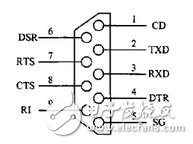
February 17, 2021