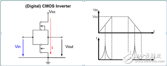
As we all know, MSP430 is known for its ultra-low power consumption. However, many users react. In practical applications, when measuring the power consumption of the MSP430, the measurement results are far from the MSP430 data sheet. In fact, here mainly involves two aspects: 1. How to use MSP430 to properly design hardware and software to maximize the low power consumption of the entire application? 2. How to measure the power consumption of the MSP430? On how to measure the power consumption of the MSP430, let me share my personal experience. First, the processing of unused GPIO In order to maximize the low power consumption of the MSP430, the GPIO that is not used by the MSP430 should be set as an output; or it can be set as an input, but the level of the pin is fixed, and the pin can be connected through an external circuit. To Vcc or GND, the internal pull-up resistor can also be enabled to fix the pin level. For the MSP430, in most cases, the measured power consumption does not match the datasheet due to improper handling of the unused GPIOs of the MSP430. By default, the MSP430's GPIO is used as an input, and its equivalent circuit is shown in the figure below, in push-pull mode: When the GPIO pin is configured as an input pin and the external level is floating (0 "Vin "Vcc"), the on-current of the internal MOSFETs is itself at an unstable value, which causes the overall power consumption to rise. High, the schematic diagram is shown in the right half of the figure above. In addition, too high or too low temperature will aggravate this instability, and when the supply voltage rises, the conduction current of the MOSFETs itself will also become larger. Therefore, under the dual effects of high pressure and low temperature, power consumption will rise. Second, the determination of the preconditions The MSP430 data sheet provides power consumption in various modes, including the relevant preconditions, including: measurement temperature, supply voltage, clock source of the system clock, system clock size, CPU frequency, MSP430 working mode, and acTIve modules (eg Brownout: BOR, WDT). Therefore, be sure to pay attention to these preconditions when verifying the power consumption of the MSP430 in a particular mode. If you want to compare power consumption with other MCUs, it is important to remember to compare them under the same preconditions. The MSP430's BOR function is turned on in all 7 LPM modes and is almost zero-power. Third, measure the power consumption of MSP430 in LPM4/LPM3 mode In order to more accurately measure the power consumption of the entire user application and minimize the power consumption of the entire application, it is recommended to measure the overall power consumption of the board when the MSP430 is in LPM4/LPM3 mode. In the LPM4, LPM3 mode, after the MSP430 power consumption is adjusted to the data sheet, on this basis, the power consumption measurement in other cases is performed. 1. Writing low power test program a. LPM4 low power test program writing For the preparation of the LPM4 low-power test program, it is recommended to refer to the Wolverine MSP430FR5969 LPM4 code example. As shown in the figure below, the main precautions are: When used as an input, the GPIO state is fixed so that it is not affected by the external floating level. In the example, the GPIO is set to input, but its internal pull-down resistor is enabled to fix the state of the GPIO. Of course, you can also configure the GPIO as an output directly. Also, be careful to turn off unnecessary modules to avoid unnecessary power consumption increases. For example: MSP430FR5739, under LPM4, remember to turn off the reference source REF. REFCTL0 |= REFTCOFF; REFCTL0 &= ~REFON; b. LPM3 low power test program writing First of all, you need to understand that for the power consumption test in LPM3 mode, you need to select the clock source of ACLK, whether it is internal VLO or LFXT1. Because under LPM3, the MSP430's system clock is only available for ACLK, neither MCLK nor SMCLK is available. When the clock source selection of ACLK is different, the power consumption of the MSP430 is different in LPM3 mode. Take the MSP430G2553 as an example. The data sheet states that under LPM3, when ACLK=LFXT1, the power consumption is about 0.7uA. Under LPM3, when ACLK=VLO, the power consumption is about 0.5uA. In addition, in the measurement, to ensure that the program successfully went to LPM3 mode. It is best to have an indication before entering the LPM3, such as letting an LED light on for 0.5s and then extinguishing. Be sure to remember to turn off the LED when entering the LPM3, because an LED light is on, it is very power-consuming, sometimes up to 2mA. And why do you have instructions? Because when using LFXT1 as the ACLK clock source, it is necessary to check whether LFXT1 is successfully oscillated in the program. In case the user forgets to solder LFXT1, or the low frequency crystal does not start, it will cause the program to remain in the check flag. Enter LPM3. In these cases, if there is no indication, when measuring power consumption, it will be found that the measurement results do not match the power consumption under LPM3 in the data sheet. In addition, remember to determine whether the LFXT1 starts to oscillate. Never use an oscilloscope to measure the pins of the low-frequency crystal directly. Because the LFXT1 itself is very fragile, it will stop vibrating once there is fluctuation outside. It is recommended to use LFXT1 as the ACLK clock source, then output the ACLK from the corresponding tube and observe it with an oscilloscope.
- Overload Protector Power Strip protects electronics from over current damage.
- Power Strip with Individual Switches controls power of each connected electrical devices separately and individually.
- Power bar with main double break switch and Individual Switches as well. USB Ports Power Strip Individual Switches bring you convenient charging solution.
- Multiple outlets Receptacle Outlet with Switches allowing you to plug in various electrical devices at the same time.
- Qualified Power Cord allowing you extend the outlet 6 feet (2 meters) away from the wall or even further.
- Pure PC/ABS flame retardant housing.
Individual Switches Power Strip with Individual Switches, Overload Protector Power Strip, USB Ports Power Strip Individual Switches, Receptacle Outlet with Switches ZhongShan JITONGLONG Plastic Hardware Co. Ltd. , https://www.toukoo-electronics.com


March 04, 2020