1 Hardware platform Blackfin561 is a high-performance fixed-point DSP video processing chip in the Blackfin series. Its main frequency is up to 750MHz, and its core contains 2 16-bit multipliers MAC, 2 40-bit accumulator ALUs, 4 8-bit video ALUs, and 1 40-bit shifter. The two sets of data address generators (DAGs) in the chip can provide addresses for accessing dual operands from memory at the same time, and can handle 1200M multiply-add operations per second. The chip has dedicated video signal processing instructions and 100KB of on-chip L1 memory (16KB of instruction cache, 16KB of instruction SRAM, 64KB of data Cache / SRAM, 4KB of temporary data SRAM), 128KB of on-chip L2 memory SRAM, and With dynamic power management function. In addition, the Blackfin processor also includes a wealth of peripheral interfaces, including EBIU interfaces (4 128MB SDRAM interfaces, 4 1MB asynchronous memory interfaces), 3 timers / counters, 1 UART, 1 SPI interface, 2 synchronous serial Interface and 1 parallel peripheral interface (support ITU-656 data format), etc. The Blackfin processor fully embodies the algorithm support for media applications (especially video applications). 1.2 Video encoder platform based on ADSP-BF561 The hardware structure of the Blackfin561 video encoder is shown in Figure 1. The hardware platform uses ADI's ADSP-BF561EZ-kitLite evaluation board. This evaluation board includes an ADSP-BF561 processor, 32MBSDRAM and 4MBFlash. The AD-V1836 audio codec in the board can be connected to 4 input / 6 output audio interfaces, while the ADV7183 video decoder and ADV7171 video encoder can be connected to 3 Input / 3 output video interface In addition, the evaluation board also includes a UART interface, a USB debugging interface and a JTAG debugging interface. In Figure 1, the analog video signal input by the camera is converted into a digital signal by the video chip ADV7183A. This signal is compressed from the Blackfin561 PPI1 (parallel external interface) into the Blackfin561 chip, and the compressed code stream is converted from ADSP-ADV7179 after conversion BF561's PPI2 output. This system can load programs through Flash, and supports serial port and network transmission. Data such as original images and reference frames during the encoding process can be stored in SDRAM. Video codec standards mainly include two series: one is MPEG series, and the other is H.26X series. Among them, MPEG series standards are formulated by ISO / IEC organization (International Organization for Standardization), and H.26X series standards are formulated by ITU-T (International Telecommunication Union). I-TU-T standards include H.261, H.262, H.263, H.264, etc., mainly used for real-time video communication, such as video conferencing. The H.264 video compression algorithm uses a block-based hybrid coding method similar to H.263 and MPEG-4. It uses two coding modes: intra-frame coding (Intra) and inter-frame coding (Inter). Compared with previous coding standards, in order to improve coding efficiency, compression ratio and image quality, H.264 uses the following new coding technology: (1) H.264 divides the video coding system into two layers: video coding layer (VCL, VideoCodingLayer) and network abstraction layer (NAL, NetworkAbstracTIonLayer) according to function. Among them, VCL is used to complete the efficient compression of video sequences, and NAL is used to standardize the format of video data, mainly providing header information to suit the transmission and storage of various media. (2) Advanced intra prediction, which uses 4 & TImes; 4 prediction for macroblocks with more spatial detail information, and 16 & TImes; 16 prediction mode for flat areas, the former has 9 prediction methods, the latter There are 4 prediction methods. (3) Inter prediction uses more block division types. The standard defines 7 different macroblock partitions (16 & TImes; 16, 16 × 8, 8 × 16) and sub-macroblock partitions (8 × 8, 8 × 4, 4 × 8, 4 × 4). Due to the use of smaller blocks and adaptive coding, the amount of data for prediction residuals can be reduced, thereby further reducing the code rate. (4) High-precision motion prediction based on 1/4 pixel accuracy. (5) Multi-reference frame prediction is possible. When coding between frames, up to 5 different reference frames can be selected. (6) Integer conversion (DCT / IDCT). For the 4 × 4 integer transform technology of the residual image, fixed-point arithmetic is used to replace the floating-point arithmetic in the conventional DCT transform. In order to reduce the coding time, it is also more suitable for transplantation to the hardware platform. (7) H.264 / AVC supports two entropy coding methods, namely CAVLC (Context-based Adaptive Variable Length Coding) and CABAC (Context-based Adaptive Arithmetic Coding). Among them, CAVLC has higher error resistance, but the coding efficiency is lower than that of CABAC; while CABAC has high coding efficiency, but requires more calculation and storage capacity. These new technologies of H.264 make the moving image compression technology a big step forward. It has better compression performance than MPEG-4 and H.263, and can be applied to high performance such as Internet, digital video, DVD and TV broadcasting. The field of video compression. 3 Implementation of H.264 video encoding algorithm The improvement of H.264 in DSP requires the following three steps: C algorithm optimization on the PC, program migration from the PC to the DSP, and code optimization on the DSP platform. 3.1 C algorithm optimization on PC According to the system requirements, this design selects ITU's Jm8.5 version baseline profile as the standard algorithm software. ITU's reference software JM is designed based on PC, so it can achieve higher coding effect. When porting video codec software to DSP, DSP system resources should be considered. The main factor that should be considered is system space (including program space and data space). The ported code has some understanding. Figure 2 shows the algorithm structure of H.264. After understanding the algorithm structure, you also need to determine the part that requires a large amount of calculation and takes a long time in the implementation of the encoding algorithm. VC6's own profile analysis tool shows that the intra-frame and inter-frame coding parts occupy more than 60% of the overall running time. Among them, ME (MoveEstimation, motion estimation) takes up more of it. Therefore, the focus of porting and optimization should be on the motion estimation part, so the code structure should be adjusted.
Antenk DIN41612 Connectors are a versatile two piece Pcb Connector set with feaures useful for many applications including connections for plug-in card and back-panel wiring, PCB to PCB attachment and peripheral connections for external interfaces. Features include a multitude of body sizes and styles with options that include selective contact loading, make and break contacts, contact lead length choices and contact plating variations each in .100" [2.54mm] or .200" [5.08mm] centerline spacing.
The Din 41612 standard covers a series of two-piece backplane connectors widely used in rack-based telecommunication, computing, process control, medical, industrial automation, test and measurement and military/aerospace systems where long-term reliability is required. They consist of one to three rows of contacts in combinations of 16, 32, 48, 64, or 96 contacts on a 0.1-inch (2.54 mm) grid pitch. The 3 rows are labelled a, b and c and connectors up to 64 way if using a 96 way body can use either rows a+b or a+c. DIN 41612 Signal connectors can be rated to 1.5 amps per signal pin, at 500 volts, although these figures may be de-rated according to safety requirements or environmental conditions. Several hybrid power and coaxial configurations are available that can handle up to 5.6A or even 15A. This wealth of variations explains the very wide range of applications that they`re put to. For over 30 years these DIN 41612 `Euro Card` connectors to IEC 60603-2 have offered a highly reliable system for board interconnects. Precision contact density, low mating forces, a two piece protective design and many contact termination styles offer unlimited design opportunities. Termination methods include – straight PC, solder eyelet, wire wrap, crimp and [press fit" terminals. Insertion and removal force are controlled, and three durability grades are available. Standardisation of the connectors is a prerequisite for open systems, where users expect components from different suppliers to operate together; ept and Conec DIN 41612 are therefore fully intermateable with all other similarly compliant products from other manufacturers like Harting, Erni, Hirose and TE Connectivity, etc.
DIN 41612 Connectors are widely used in rack-based electrical systems. The standard performance of these connectors is a 2 A per pin current carrying capacity and 500 V working voltage. Both figures may be variable due to safety and environmental conditions.
Types
Features and Benefits of Din41612 Connector:
Uses
Applications of Din41612 Connector:
Din41612 Connector Din41612 Connector,Din 41612,Eurocard Connector Din41612,Male Din41612 Connector ShenZhen Antenk Electronics Co,Ltd , https://www.antenk.com
1.1 ADSP-BF561 processor
2 Main features of H.264 video compression coding algorithm
(8) Adopt new loop filter technology and entropy coding technology.
The most common connector in the DIN product line is type C, which is widely used in VMEbus systems, the DIN 41612 standard has been upgraded to meet international standards IEC 60603-2 and EN 60603-2. In the past, ept used a comb supported press-fit tool for their type C and B press-fit female connectors. To be more competitive, ept has changed to flat-rock technology (just a flat piece of steel pushed on the top of the connector) as used by many other manufacturers.
Number of contacts varies
Many variations of housing material, including different types of metal and plastic
Both angled and straight versions
Male and female
C,R,B,Q Type DIN41612 Connectors
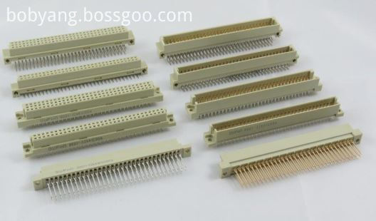
Half C, R, B & Q Type DIN41612 Connectors
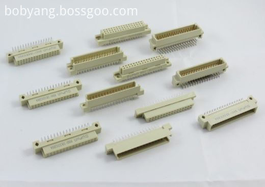
1/3 C,R, B & Q Type DIN41612 Connectors
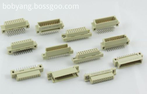
H, F, H+F & M type DIN41612 Connectors
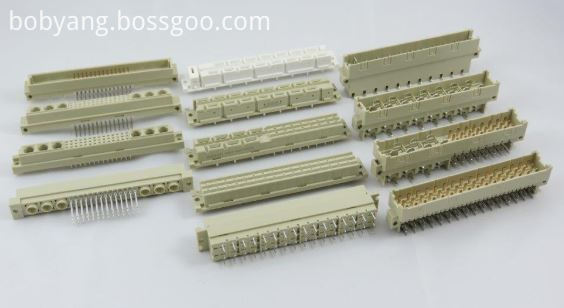
IDC Type DIN41612 Connectors
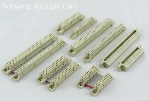
Female Cable Connector
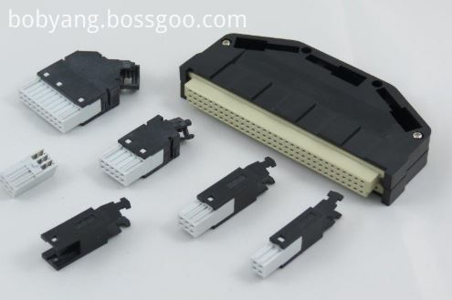
High Pin Count DIN41612 Connectors
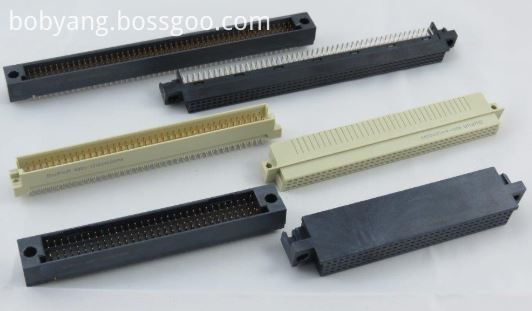
Shroud DIN41612 Connectors
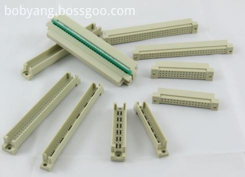
• Indirect mating (male/female)
• Automated production processes
• Continuous quality assurance
• 3-160 contacts
• Complete interconnection system
• Numerous interface connectors
• A wide variety of hoods
• Many termination technologies provide for the lowest installed cost
• Contacts selectively gold-plated
• Tinned terminations for increased solderability
The primary use of DIN 41612 connectors are PCB connectors and motherboards, the main acceptance would be their board to board reliable connections.
Applications
• Data centers
• Storage
• Servers
• Base stations
• Telecommunications equipment
• Backplane and motherboard assemblies
• Switching systems
• Modular rack systems
• Power automation
• Distributed control systems in
industrial control
• Programmable logic controllers (PLC)
• Robotics
• Test and lab equipment
• Energy distribution
• Monitoring equipment
This is not a definitive list of applications for this product. It represents some of the more common uses.
April 16, 2020