Compared to the old, bulky cathode ray tube (CRT) displays used in the past, flat panel digital TVs and displays are now much thinner. These new flat-screen TVs are very attractive to consumers because they take up less space. To help meet consumer demand and make such digital devices thinner, some manufacturers have turned to LLC resonant half-bridge converters to drive the light-emitting diode (LED) backlight of these devices. This is because the zero-voltage soft switching (ZVS) achieved with this topology can result in a more efficient high-power density design and requires fewer heat-dissipating components than a hard-switching topology. One problem with this type of topology design is that the LLC dc / dc transfer function will change significantly as the load changes. However, this will make the establishment of LLC controller and compensation current loop in the LED driver more complicated. To simplify this design process, this article will discuss a design method called pulse width modulation (PWM) LED brightness adjustment, which allows the LED load to change with the brightness adjustment while keeping the dc / dc transfer function constant. Study on the transfer function (M (f)) of the LLC resonant half-bridge dc / dc LLC resonant half-bridge controller dc / dc (see Figure 1) is a pulse frequency modulation (PFM) control topology. Half-bridge FETs (QA and QB) drive 180 out of phase and use a voltage controlled oscillator (VCO) to adjust / control the frequency. This in turn can adjust the voltage divider impedance formed by the resonant inductor (Lr), the transformer magnetic inductance (LM), the reflected equivalent impedance (RE) and the resonant capacitor (Cr) for adjustment. Only the voltage developed in the LM is reflected to the secondary coil through the transformer turns ratio (a1). Figure 1 LLC resonant half-bridge / controller We can standardize and simplify the use of the first harmonic approximation transfer function M (f). In Equation 4 of M (f), the normalized frequency (fn) is defined as the switching frequency divided by the resonance frequency (fO). Although it is only an approximation method, this simplified equation is very useful in understanding how M (f) changes with input voltage, load, and switching frequency. Adjust dc current to adjust LED brightness One way to achieve LED brightness adjustment in LLC resonant LED drivers is to adjust the dc current through the LED. There is a problem with this: After the DC current changes, the LLC output impedance also changes accordingly. If not considered carefully, this change will bring about changes in M ​​(f), thus making the LED driver design more complicated. Problems caused by load changes Designing a half-bridge converter is not an easy task. The designer should choose the magnetizing inductance (LM) according to ZVS requirements. They also have to adjust a1, Cr and Lr to obtain the ideal M (f) and frequency operating range. However, M (f) will change with Q, and Q will change with output load (RL). See Figure 2 for details. The M (f) change of the resonant LLC half-bridge LED will make voltage loop compensation and transformer selection more difficult, complicated, and confusing, because there are too many changes to consider during the design process. Figure 2 M (f) varies with load. The constantly changing LLC gain curve (M (f)) will cause voltage control oscillator (VCO) control problems in the feedback loop. The VCO is generally controlled by a feedback error amplifier (EA (see Figure 1)). The switching frequency decreases as the EA output increases to increase the LLC gain, and increases when the EA output decreases. Ideally, in an LLC half-bridge design, the M (f) gain needs to start at its minimum value at its maximum switching frequency, while M (f) rises with decreasing frequency. The ideal M (f) range during normal operation is the right part of the dotted line (see Figure 2). We call this area the inductance area, at which time LLC works under ZVS. The left side of the dotted line is the capacitor area, in this area there is no ZVS on the main switch node. During large signal transients, the EA will drive the VCO, requiring a lower switching frequency to increase the gain. As a result, the M (f) gain works in the area to the left of the dashed line, and may not reach the ideal gain and cannot meet the control loop requirements. At this time, ZVS is lost, and the feedback loop will keep the LLC controller locked in this area. Now, the feedback error amplifier attempts to require a lower switching frequency to increase the gain that the power stage cannot reach, because the converter may work in the right area of ​​the dotted line in FIG. When ZVS is lost, FETs QA and QB consume more power, and the FET will be damaged due to overheating. In order to avoid this problem in the design, it is necessary to analyze all M (f) curves, and then appropriately limit the minimum switching frequency (f) to prevent the converter (M (f)) from working on the left side of the dotted line in Figure 2 region. PWM brightness adjustment simplifies the design process For LLC resonant half-bridge LED drivers that require brightness adjustment, one way to simplify the design process is to use a technique called PWM brightness adjustment. Figure 3 shows the functional schematic of an LLC converter, and its LLC controller uses this PWM brightness adjustment technique. In our example, we used UCC25710. Figure 3 LLC half-bridge LED driver using PWM dimming technology. This technique utilizes a fixed low-frequency signal (DIM) that controls the FET QC, which is logically added to the QA and QB FET drivers. When the DIM signal is high, the LED backlight string is controlled at a fixed peak current (VRS / RS). Once DIM goes low, QA, QB, and QC are turned off immediately. After QA, QB, and QC are turned off, the LED diode stops conducting, and the output capacitor (COUT) stores energy to start the next DIM cycle on time. For more details, see the waveform shown in Figure 4. Figure 4 PWM brightness adjustment waveform By adjusting the duty cycle (D) of the DIM signal, the average diode current (ID) can be adjusted to control the LED brightness. Although the LLC resonant half-bridge powers the LED from the primary stage to the secondary stage, the load (RL) to LLC transfer function (M (f)) is still constant, even if the average LED current varies with the duty cycle. When using fixed RL and given Lr, Cr and LM, the equivalent reflected impedance (RE) is constant and Q remains unchanged. At this time, only one M (f) curve is obtained, which changes with frequency (see FIG. 5), and is not affected by the multiple curves (see FIG. 2) obtained by the traditional LED brightness adjustment method using the variable RL. Only one M (f) curve is processed in the design, making loop compensation and transformer selection easier, thereby simplifying the design process. In addition, when setting the minimum switching frequency, you need to pay attention to another curve to ensure that ZVS is maintained. At this time, the minimum f is set to the peak value of the single M (f) curve (see Figure 5). Figure 5 M (f) driving LED using PWM brightness adjustment technology It is not easy to design an LLC resonant half-bridge converter for LED driving. The dc / dc gain of traditional LLC will vary widely with load. We need to evaluate many gain curves. This makes loop compensation and transformer design / selection more complicated and confusing. To simplify the design process, it is an ideal choice to use LLC and PWM brightness adjustment technology in combination. This is because LLC will bear a fixed load (RL) during power supply, but the LED current will change during brightness adjustment. As a result, the LLC gain changes less, making loop compensation and transformer selection / design easier. remote control car motor,rc boat engine,rc helicopter motor,slot car motors,toy motor price,toy dc motor Shenzhen Maintex Intelligent Control Co., Ltd. , https://www.maintexmotor.com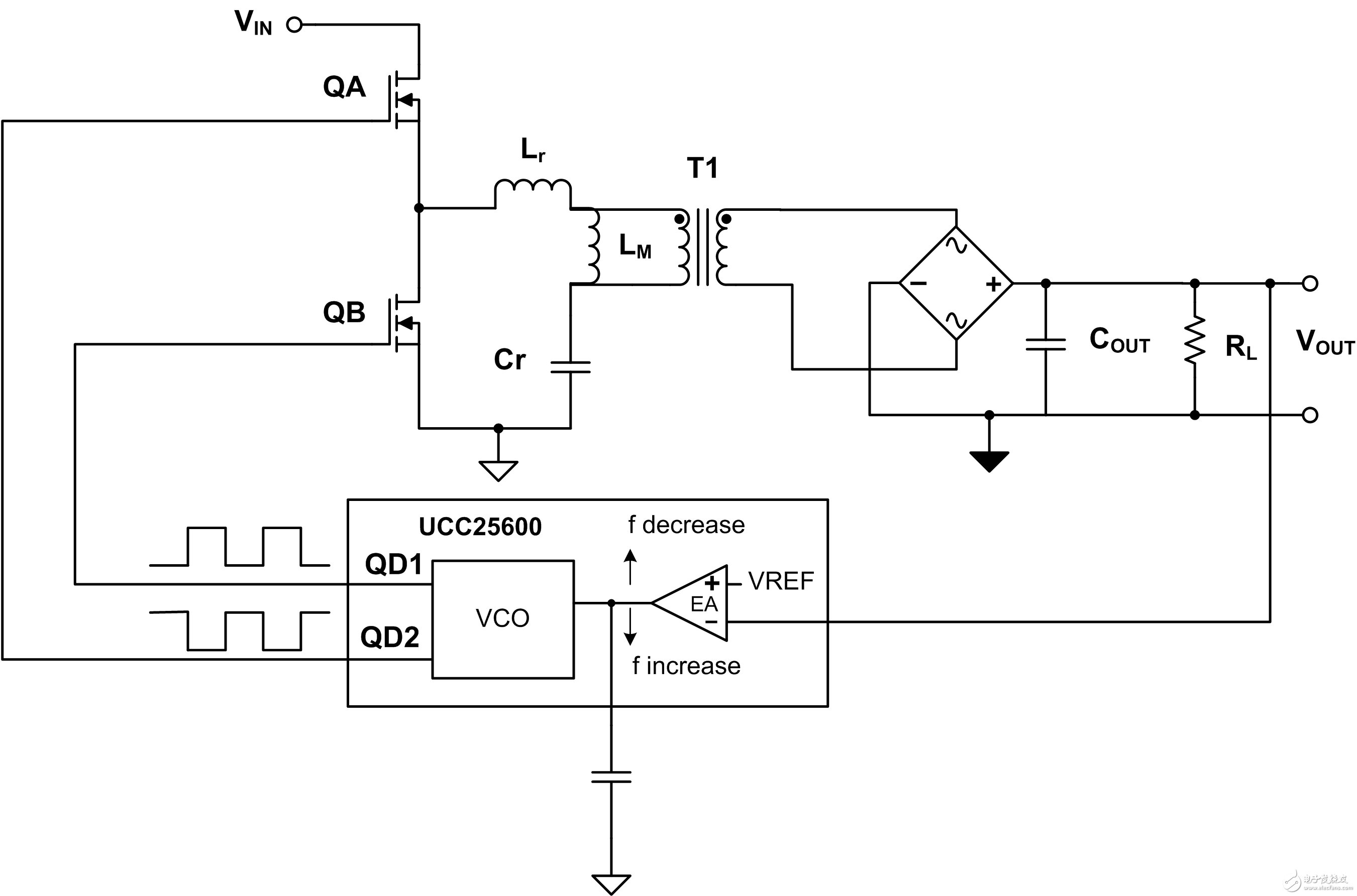


July 25, 2020