The Infineon HID headlamps and PFC control solution consists of five MOSFETs, two high voltage drivers, one PFC controller and one HID lamp ballast controller. The specific circuit is shown below. . This article refers to the address: http:// Schematic diagram of Infineon HID headlamps and PFC control scheme. The MOSFET can be selected from Infineon's N-channel MOSFET (500V or 600V CoolMOS C3/CoolMOS CP). The PFC controller can be selected from Infineon's DCM PFC-IC (TDA4863-2) or CCM PFC-IC (ICE1PCS01/02). The active power factor controller TDA4863-2 is the latest PFC-DCM (discontinuous conduction mode) control IC from Infineon for switching power supplies (SMPS). The first two generations are TDA4862 and TDA4863. They are optimized for providing very compact and cost-effective PFC solutions for electronic ballasts and offline SMPS, fully compatible with world standards. By using a zero current detector for discontinuous modes of operation, they allow a power factor close to 1 and outstanding THD to be achieved. The main features of the TDA4862, TDA4863 and TDA4863-2 include: 1) power factor close to 1; 2) control boost converter like active harmonic filter for lower THD; 3) low current start; 4) Zero current detector for discontinuous operation mode; 5) output overvoltage protection; 6) output undervoltage lockout; 7) internal start timer; 8) totem pole output with active shutdown; 9) internal edge blanking LEB; 10) sinusoidal current consumption. Compared to the TD4862, the TDA4863 and TDA4863-2 improvements are: 1) very low startup current; 2) very low comparator and multiplier offset; 3) high complexity amplifier for low distortion interference caused by MOSFET switching; ) More accurate overvoltage threshold; 5) Higher gate drive capability (only for TD4863-2). The active power factor controller ICE1PCS01/02 is an 8-inch control IC from Infineon for active CCM (Continuous Conduction Mode) power factor correction converters. The unique average current control allows for low THD at all load ranges and excellent Compensation of line voltage varations. The soft-start and the open-loop-protection provide high reliability and optimum operating conditions for SIC(silicon carbide) diodes. ICE2PCS01/02 are the 2nd generation of Continuous Conduction Mode (CCM) PFC controllers, which Employ BiCMOS technology. Compared to the first generation of ICE1PCS01/02, the new ICs have lower internal reference trimmed at 3V. They also have other advantages such as wider Vcc operating range, improved internal oscillator and additional direct bulk capacitor over-voltage protection. Major Features include: Ease of use with few external components 2. Average current control 3. External current and voltage loop compensation for greater user fexibility 4. Programmable switching (50-250kHz) for ICE1PCS01/ICE2PCS01 5. Trimmed internal fixed switching frequency for ICE1PCS02/ICE2PCS02 (65kHz+5% at 25oC) 6. Direct sensing, input brown-out detection with hysteresis for ICE1PCS02/ICE2PCS02 7. Max. duty cycle of 95% (typ) 8. Trimmed internal reference voltage (5V+2%) for ICE1PCS01/02 9. Vcc under-voltage lock-out 10. Cycle by cycle peak current limit. 11. Output over-voltage protection 12. Open loop detection 13. Output under-voltage detection 14. Enhanced dynamic response 15. Soft overcurrent protection 16. Fulfills class D spec. of IEC1000-3-2
Rigid PCB is a kind of Printed Circuit Board, and is the largest number of PCB manufactured. It is made of solid substrate material, which can effectively prevent the distortion of the circuit board. Perhaps the most common rigid PCB is the computer motherboard. The motherboard is a multi-layer PCB designed to distribute power from the power supply while allowing communication between all components of the computer, such as CPU, GPU and RAM.
Multilayer Rigid PCB Stackup
Learn more about JHY PCB by exploring the manufacturing capability of Rigid Printed Circuit Board below. We can do more than you can imagine.
Item
Manufacturing Capability
PCB Layers
1-26L (TG135 TG150 TG170 TG180)
Laminate
FR-4, FR- 406, 370 HR ,IT180A,CEM-1, CEM-3,FR1,FR2,94HB,PTFE,etc.
Brand of Laminate
Kingboard,Shengyi,Nanya,Isola,Rogers,etc.
Max Board Size
1-2layers: 1000mm * 600mm
Multilayer PCB: 600* 600mm
Board Thickness
0.1-4.0 mm
Board Thickness Tolerance
±10%
Copper Thickness
1-10 oz
Min Mechanical Drilling Hole Size
4mil(0.10mm)
Min Laser Drilling Hole Size
3mil(0.075mm
Min Line Width/Line Space
2/2mil
Surface Finishes
OSP, HASL, HASL Lead-Free (HASL LF), Immersion Gold(ENIG), Immersion Silver, Immersion Tin, Plated Gold, etc.
Solder Mask Colors
Green, Red, White, Black, Blue, Yellow, Orange, Purple, Gray.
Silkscreen Colors
Black, White, Yellow.
Electrical Testing
Fixture and Flying Probe
Other Testing
AOI, X-Ray(AU&NI), Two-dimension Measurement, Hole Copper Instrument, Impedance Test, Metalloscope, Peeling Strength Tester, Solderability Test, Logic Contamination Test
Special Capabilities
Thick Copper, Thick Gold(60μ"), Gold Finger, Blind and Buried Hole, Countersink Hole, Semi-hole, Peelable Mask, Carbon Ink, Impedance control+/- 10%, etc.
Additional information Rigid PCB Rigid PCB,Fr4 PCB,Rigid Circuit Board,Rigid Printed Circuit Board JingHongYi PCB (HK) Co., Limited , https://www.pcbjhy.com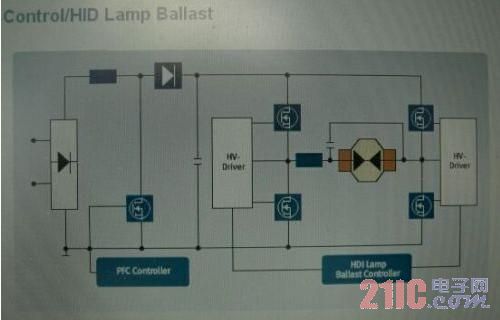
Rigid PCB , the largest number of PCB manufactured
What is Rigid PCB - Rigid PCB Definition
Rigid PCB can be used in any position where the PCB itself needs to be set to a shape and maintained during the remaining life of the equipment. Rigid PCBs can be anything from simple single-layer PCBs to eight or ten-layer multi-layer PCBs.
Rigid PCB and Flexible PCB are totally different. One is flexible and the other is rigid. Therefore, their application scenarios are different. In addition, there are Rigid Flex PCB . There are similarities between them. However, all rigid PCB have single-layer, double-layer or multi-layer structure, so they have common application scope. This is the case.

Some characteristics of rigid PCB
Rigid PCB Manufacturing
Rigid PCB is made up of different layers that are joined together using adhesive and heat, providing a solid shape to board material. Following layers are used to develop a rigid PCB.
Substrate Layer - rigid PCB material


Copper Layer
Solder Mask Layer
Silkscreen Layer

The differences between Rigid PCB And Flexible PCB
When to Use Rigid and When to Use Flexible
Rigid PCB Applications
Rigid Printed Circuit Board Manufacturer: Guaranteed Quick Delivery
JHY PCB is committed to providing the highest quality rigid Printed Circuit Boards at competitive prices. As the name suggests, these PCBs use an inflexible, solid, and rigid substrate material such as fiberglass, which prohibits these boards from bending. We can provide high-quality, and performance-oriented rigid printed circuit boards in diverse specifications.
Different Types of Rigid PCB Provided by JHY PCB
Matt: Green, Blue, Black.
October 12, 2019