An ammeter is a device used to measure electric current in both AC and DC circuits. In circuit diagrams, the symbol for an ammeter is typically represented as a circle with the letter "A" inside. The standard unit of current is "A" (ampere). This article provides a comprehensive guide on how to use a regular ammeter as well as a clamp-type ammeter, along with their respective diagrams for better understanding.
How to Use an Ammeter
Key Rules for Using an Ammeter:
- The ammeter must be connected in series with the circuit being measured. Connecting it in parallel can cause a short circuit.
- Current should enter through the “+†terminal and exit through the “-†terminal. Reversing the polarity will cause the needle to move backward.
- Ensure that the current being measured does not exceed the ammeter’s range. A test touch method can be used to check if the range is appropriate.
- Never connect the ammeter directly across the power supply terminals without passing through a load. This can cause excessive current flow, leading to damage to the ammeter, power supply, or wiring.
Reading the Ammeter:
- Determine the scale range of the ammeter (e.g., 0–3A or 0–0.6A).
- Identify the smallest division on the scale (for example, 0.1A for 0–3A, and 0.02A for 0–0.6A).
- Observe the needle position from the front to ensure accuracy.
Preparation Before Using the Ammeter:
- Zero the ammeter by adjusting the zero button using a flat-head screwdriver.
- Select the appropriate range either based on experience or by using the test touch method.
Step-by-Step Usage of an Ammeter:
- Connect the Ammeter: The ammeter must be placed in series with the circuit under test. Current should flow into the “+†terminal and out of the “-†terminal. Never connect the ammeter directly to the power supply without a load, as this could result in damage.
- Select the Range: An ammeter usually has three terminals. If connected between “+†and “0.6â€, the range is 0.6A, and the lower scale should be read. If connected between “+†and “3â€, the range is 3A, and the upper scale is used. Before starting, estimate the current value. If it's less than 0.6A, choose the 0.6A range; otherwise, use the 3A range. If unsure, perform a test touch to determine the correct range.
- Test the Circuit: After connecting the circuit according to the diagram, perform a test. If the needle doesn't move, the circuit may be open. If it moves in the wrong direction, the polarity is reversed. If the needle swings too far, the range is too small; if it barely moves, the range is too large. Adjust accordingly before proceeding with the experiment.
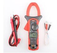
Using a Clamp-Type Ammeter
Steps to Use a Clamp Meter:
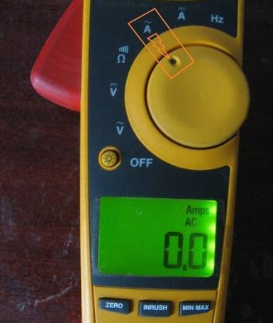
- Select the Correct Setting: Choose the appropriate mode (AC or DC) depending on the type of current being measured. For example, select the AC current setting as shown in the figure.
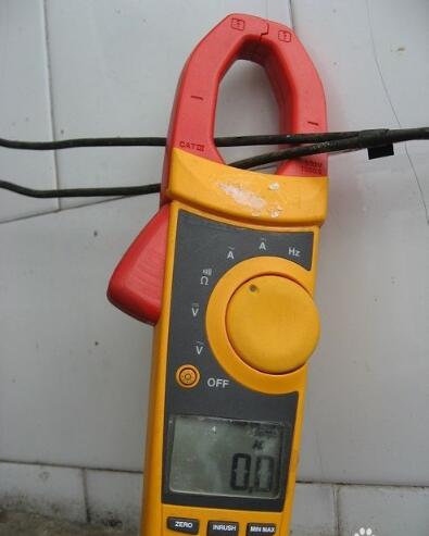
- Open the Jaws: Open the jaws of the clamp meter and place them around a single conductor in the circuit. Incorrect placement, such as clamping around multiple wires or not enclosing the wire at all, can lead to incorrect readings or no reading at all.
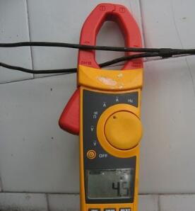
- Correct Placement: Ensure only one wire passes through the jaws. If two wires are present, measure each separately. The readings should be similar. If they differ significantly, there may be a fault or leakage in the circuit. A correct setup would show a measured current of 4.5A, as shown in the figure below.
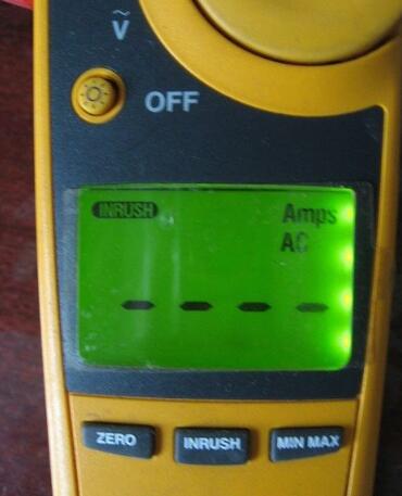
- Measuring Inrush Current: To measure the starting current of an appliance, press the “INRUSH†button before turning on the device. This feature helps capture the initial surge of current when the appliance starts up.
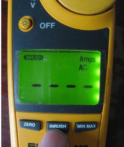
- Incorrect Reading: If the appliance does not start after pressing the “INRUSH†button, the display may show an error or no reading, as shown in the figure below.
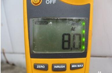
- Starting Current Measurement: Once the appliance is turned on, the measured starting current will appear on the screen, as shown in the figure below.
Important Precautions:
- Always ensure the clamp meter is set to the correct mode (AC or DC). Choosing the wrong setting will result in inaccurate readings.
- When measuring inrush current, press the “INRUSH†button before starting the appliance. Failing to do so may prevent the meter from detecting the maximum starting current.
Pushbutton Switches
There are many types of Push-Button Switches, which can be divided into ordinary button type, mushroom head type, self-locking type, self-resetting type, rotary handle type, with indicator light type, illuminated symbol type and key type etc.The push button switch is a main electric appliance with a simple structure and a wide application. In the electrical automatic control circuit, it is used to manually send out control signals to control contactors, relays, electromagnetic starters and so on.
Our company's Pushbutton can be divided into these series(as follow):
XB2-E Series Pushbutton Switch
XB2-B Series Pushbutton Switch
XB4 series Pushbutton Switch
XB5 Series Pushbutton Switch
SDL seris Pushbutton Switch
Control Station
Crane Control Switch
Pushbutton Switches,COB 61 Push Button Switch,XB2 Pushbutton Switch,COB Pushbutton Switch
Ningbo Bond Industrial Electric Co., Ltd. , https://www.bondelectro.com
September 28, 2025