How much performance can the MAC of MAXQ2000 play? This application note uses an audio filter as an example to explain this problem, and gives the performance supported by MAXQ2000 quantitatively.
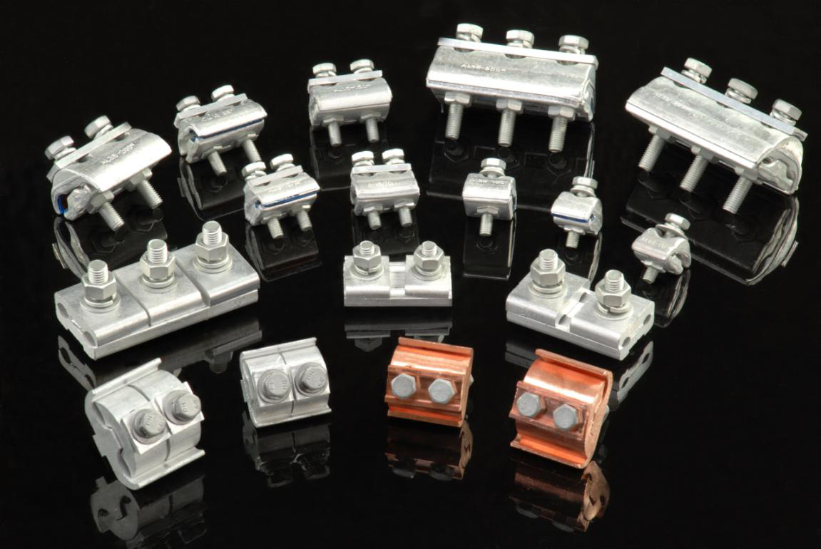
The connection of the parallel groove clamp for the medium and small section of the aluminum stranded wire or the overhead stranded wire and the steel core aluminum stranded wire strand in the position where the tension is not applied is also used for the jumper connection of the non-linear tower. Parallel Clamp is a parallel connection wire to transmit the electrical load of the contact fittings. Parallel Jaw Clamps are widely used.
The following are the model parameters we product:
We warmly welcome friends both domestic and abroad to visit our company, if you have any questions, please contact with us directly.
Parallel Clamp Parallel Groove Clamp,Parallel Clamp,Parallel Jaw Clamps, Parallel Action Clamp FUZHOU SINGREE IMP.& EXP.CO.,LTD. , https://www.cninsulators.com
The hardware required in this application note includes the MAXQ2000 evaluation board and a simple circuit to interface with the computer speaker.
The MAXQ2000 evaluation board now available is the best tool for understanding the performance of MAXQ2000. It includes an LCD panel and a set of LEDs. All I / O pins of the MAXQ2000 can be accessed through the evaluation board. The MAX1407 ADC / DAC integrated in the EV kit can be used for audio output.
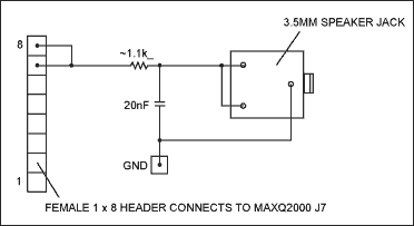
The required second part of the hardware can be easily realized by the circuit experiment board. The circuit used in the demonstration is shown in Figure 1. It uses a 1 x 8 hole socket to connect to the MAXQ2000 evaluation board at J7, which needs to be connected to any ground potential (TP1 on the MAXQ2000 evaluation board can be selected). The speaker connector can be any type. The picture shows a 3.5mm stereo jack, which can be easily connected to commonly used computer speakers. Note that the two input channels are connected in parallel, because our demonstration only uses one audio channel (mono). 
Figure 1. Other hardware required for audio playback
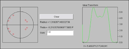
The software required for this demonstration is created and debugged using the IAR embedded platform. The platform provides a good debugging environment, using MAXQ2000 hardware debugging support. You can set breakpoints, set or read registers and memory, and view stack calls while running in a real hardware environment. Run the demo The buttons on the MAXQ2000 evaluation board are used to select filters and play filtered audio samples. Use the button SW4 to select the filter, the filter name will be displayed on the LCD (HI is high pass, LO is low pass, BP is band pass, ALL is all pass). Use button SW5 to play the audio through the selected filter. The filter can be switched during playback. Design a simple FIR filter This article uses a Java â„¢ applet to easily generate new filters. Instead of using standard windowing techniques to give the filter parameters, as shown in Figure 2, simply place a zero on the pole-zero diagram to simply "design" the filter. The applet can place a zero point anywhere on the coordinate plane and automatically update the parameters of the FIR filter required for the demonstration. Note that the demo only supports all zero filters. It is not difficult to support IIR filters, which is explained in detail in the section Supporting IIR Filters. 
Figure 2. Using a pole-zero plot to generate a simple FIR filter
The linear equation of the ordinary filter is:
y (n) + bKy (k) =
aJx (j)
Where k represents the order of the feedback part of the filter and j represents the order of the feedforward part of the filter.
An IIR filter can be simply expressed by the following formula:
y (n) = 0.5y (n-1) + x (n)-0.8x (n-1)
Some filters are classified as FIR filters and do not include the feedback part. In other words, the y part is not included in the filter characteristic equation:
y (n) = aJx (j)
y (n) = x (n)-0.2x (n-1) + 0.035x (n-3)
In any case, the filter can be reduced to a characteristic equation, which is essentially a weighted average of past inputs and outputs. The filter design generates Aj and Bk values. To efficiently calculate the filter output, hardware support that can quickly multiply and add signed numbers is required. This is the multiply-accumulate unit of MAXQ2000. Implementing a filter using a multiply-accumulate (MAC) unit The applet in the previous section can calculate filter parameters by specifying the zero coordinates in the graph. But the calculation result is a floating point number, and MAC is a pure 16-bit integer operation. To solve this problem, this demonstration uses a fixed-point value system, the 0 to 15 digits of the parameter are the values ​​to the right of the decimal point (the 16th digit represents the sign polarity). After the operation is completed, the 48-bit result in the MAC accumulator removes the remaining part by shifting.
This solution is a compromise between accuracy and speed. In many cases, the error produced by this method is negligible. For diagnostic purposes, the applet can display three curves of the calculated filter. The first curve uses 64-bit floating-point numbers to show the running state of the ideal filter. This curve is marked with “Ideal Transform†in FIG. 2.
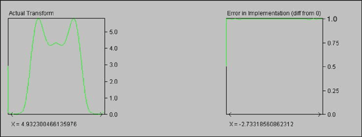
Figure 3 plots the remaining curves produced by the applet. The first curve shows the filtering effect using 16-bit fixed-point number. In many cases, the error is not obvious. The last curve is an error indicator, showing the ideal frequency response divided by the actual frequency response. Ideally, this is a straight line with Y = 1. 
Figure 3. 16-bit filter actual effect and rounding error (visually no error)
For simplicity, the applet generates the floating-point parameters required by the MAXQ® filter, so the new filter can be implemented simply by cutting and pasting it into the filter source file (data.asm file). The applet also generates two other values, the filter order (number of parameters) and the number of shifts, and the application can shift the final result appropriately. The data appears in the text box at the bottom of the applet and may be presented in the following ways: Zeroes: dc16 dc16 12, 11, 0x1000, 0x26d3, 0x1e42, 0xf9a3, 0xecde, 0xff31, 0xa94, 0x2ae, 0xfd0c, 0xff42, 0xde Shift amount: 12 Implement the filter in MAXQ assembly language To get the best performance and perform accurate performance analysis, the actual filter is implemented in assembly language, which can accurately calculate the number of cycles required to produce an output, and thus estimate the other data settings. performance.
The MAX1407 contains a 12-bit ADC. The input data is 16-bit wide, and the filter produces a 16-bit result. Although the 4 least significant bits (LSB) are not used in this application, they can still be calculated and output as a 16-bit normal analysis of their performance (CD quality audio is 16 bits).
In this example, the filter parameters are stored in the table in the code area. After selecting a filter, the application finds the appropriate filter, reads the shift number and the number of taps, and then is ready to start digital filtering. The following code applies the filter parameters: move MCNT, # 22h; signed, mult-accum, clear regs first zeroes_filterloop: move A [0], DP [0]; let's see if we are out of data cmp #W: rawaudiodata; compare to the start of the audio data lcall UROM_MOVEDP1INC; get next filter coefficient move MA, GR; mulTIply filter coefficient ... lcall UROM_MOVEDP0DEC; get next filter data move MB, GR; mulTIply audio sample ... jump e, zeroes_outofdata; stop if at the start of the audio data djnz LC [0], zeroes_filterloop zeroes_outofdata: move A [2], MC2; get MAC result HIGH move A [1], MC1; get MAC result MID move A [0], MC0; get MAC result LOW Before executing this code, LC [0] is loaded into the filter tap number, DP [0] is loaded into the current input byte address of the filter, and DP [1] is loaded into the filter parameter start address. DP [1] processes the filter parameters in an incremental manner, and DP [0] processes the input data in a decreasing manner (the most recently input data is processed first).
Since the MAC works in a single cycle, there is less processing code. Set MCNT to 22h to use signed integer. In the main loop, write MA continuously, then write MB to trigger the multiply-accumulate operation, and the result is ready in the next clock cycle. Since the accumulator is 48 bits (the result of the multiplication is 32 bits), no overflow will occur (unless there are 64,000 taps in the filter!). Performance This application handles mono 16-bit audio data and produces 8kHz output, but has not yet fully utilized the capabilities of the microcontroller. Since the filter is written in assembly language, an expression can be used to conveniently calculate the number of cycles required to calculate the FIR filter of length N. This expression can then be used to calculate the maximum filtering rate using the algorithm listed previously.
The functions for generating audio samples can be divided into three parts: initialization, filter calculation loop, and result correction. In this example, 38 cycles are required for initialization, 17 cycles for each filter parameter in the filter calculation, and 9 + (6 x S) cycles are required for the result correction, where S is the number of shifts. Generally, the number of shifts is 12, and the result is corrected to 81 cycles. Therefore, 119 + (17 x N) cycles are required to produce a filtered output. At 20MHz, the MAXQ2000 can run a 100-tap filter near 11kHz, which is already pretty good voice quality.
Now back to the front to reanalyze the application for further simplification. We will mainly focus on the filter loop because it takes up most of the cycles and is the most cumbersome.
There are also several key improvements to the loop code to increase efficiency. Note that we used pre-recorded and stored audio samples in the code area. Because MAXQ uses the Harvard architecture, it takes more time to find the code space than the data space. The functions called UROM_MOVEDP1INC and UROM_MOVEDP0DEC require 5 cycles per execution (LCALL is 2 cycles, and the function is 3 cycles internally). If the filter is stored in RAM and processes the real-time input data stored in RAM, then only two cycles are required for each (one cycle select pointer, one cycle read). If 256 words in RAM are used for the filter, BP [Offs] can be used to implement a ring buffer to store the input data. These changes can reduce the cycle time from 17 cycles to 11. Such a filter loop is shown below (the number of cycles required is listed first in the comments): zeroes_filterloop: move A [0], DP [0]; 1, let's see if we are out of data cmp #W: rawaudiodata ; 2, compare to the start of the audio data move DP [1], DP [1]; 1, select DP [1] as our acTIve pointer move GR, @DP [1] ++; 1, get next filter coefficient move MA, GR; 1, mulTIply filter coefficient ... move BP, BP; 1, select BP [Offs] as our active pointer move GR, @BP [Offs--]; 1, get next filter data move MB, GR ; 1, multiply audio sample ... jump e, zeroes_outofdata; 1, stop if at the start of the audio data djnz LC [0], zeroes_filterloop; 1 The MAXQ architecture can also be used after loading the filter and input data into RAM Another characteristic. The MAXQ instruction set is highly irrelevant, and in any operation, there are almost no restrictions on which source is used. Therefore, instead of reading the filter data and input data into the GR, it can be directly written into the MAC register. This reduces the cycle to 9 cycles. zeroes_filterloop: move A [0], DP [0]; 1, let's see if we are out of data cmp #W: rawaudiodata; 2, compare to the start of the audio data move DP [1], DP [1]; 1, select DP [1] as our active pointer move MA, @DP [1] ++; 1, multiply next filter coefficient move BP, BP; 1, select BP [Offs] as our active pointer move MB, @BP [ Offs--]; 1, multiply next filter data jump e, zeroes_outofdata; 1, stop if at the start of the audio data djnz LC [0], zeroes_filterloop; 1 The last modification can greatly improve the code. Each time through the loop, compare the current data pointer with the starting position of the audio input data to see if it crosses the boundary (MOVE A [0], DP [0] statement, CMP comparison statement, and JUMP E statement). If you set the initial audio data (the ring buffer currently being read and pointed to by BP [Offs]) to all zeros, you can omit these checks. Compared with the subsequent thousands of samples, which saves 4 cycles at a time, the RAM initialization time is negligible, and the new loop code is reduced to 5 cycles. zeroes_filterloop: move DP [1], DP [1]; 1, select DP [1] as our active pointer move MA, @DP [1] ++; 1, multiply next filter coefficient move BP, BP; 1, select BP [Offs] as our active pointer move MB, @BP [Offs--]; 1, multiply next filter data djnz LC [0], zeroes_filterloop; 1 Before returning to the performance equation, first look at the result calculation. It seems that there is currently no need to shift the 48-bit result. move A [2], MC2; get MAC result HIGH move A [1], MC1; get MAC result MID move A [0], MC0; get MAC result LOW move APC, # 0C2h; clear AP, roll modulo 4, auto -dec AP shift_loop:;; Because we use fixed point precision, we need to shift to get a real; sample value. This is not as efficient as it could be. If we had a; dedicated filter, we might make use of the shift-by-2 and shift-by-4; instructions available on MAXQ.; move AP, # 2; select HIGH MAC result move c, # 0; clear carry rrc; shift HIGH MAC result rrc; shift MID MAC result rrc; shift LOW MAC result djnz LC [1], shift_loop; shift to get result in A [0] move APC, # 0; restore accumulator normalcy move AP, # 0; use accumulator 0 One possible method is to adopt MAC again. Instead of shifting 12 bits to the right (or any value between 0 and 16), shift to the left by 16 minus the number of digits of the value (such as 4 bits to the left). This will place the result in the middle of the 16-bit word of the MAC register. Note that the actual result of shifting to the left is multiplied by a power of 2 (assuming that when starting to shift right by 12 bits, it is 16). ;; don't care about high word, since we shift left and take the; middle word.; move A [1], MC1; 1, get MAC result MID move A [0], MC0; 1, get MAC result LOW move MCNT, # 20h; 1, clear the MAC, multiply mode only move AP, # 0; 1, use accumulator 0 and # 0F000h; 2, only want the top 4 bits move MA, A [0]; 1, lower word first move MB, # 10h; 1, multiply by 2 ^ 4 move A [0], MC1R; 1, get the high word, only lowest 4 bits significant move MA, A [1]; 1, now the upper word, we want lowest 12 bits move MB, # 10h; 1, multiply by 2 ^ 4 or MC1R; 1, combine the previous result and this one;; result is in A [0]; it will take 12 cycles to calculate the result, and Not 9 + (6 x S) cycles.
Now back to the previous equation. The new equation conservatively estimates that the overhead takes 40 cycles, and each cycle iteration takes 5 cycles. Using the same 100-tap filter as before, the MAXQ2000 can handle 16-bit, 37kHz mono audio data, as shown in Table 1.
Table 1. FIR filter maximum sampling rate (20MHz MAXQ2000, loop) Filter Length (Taps) Max Rate (Hz) 50 68965.51724 100 37037.03704 150 25316.4557 200 19230.76923 250 15503.87597 300 12987.01299 350 11173.18436
For applications that require higher sampling rates, code space can be sacrificed to further improve performance. Filter parameters can be "embedded", eliminating the need to select valid pointers and loops (this technique is also called loop unrolling). The cost of this change is to increase the code space. Previously, 100 words were required to store a 100-point filter; now, 300 words are required to store (each parameter moves 2 words, and each data moves 1 Words). In a 16k word device, this cost is negligible relative to the performance improvement. The new code form is as follows: move BP, BP; select BP [Offs] as our active pointer zeroes_filtertop: move MA, # FILTERCOEFF_0; 2, multiply next filter coefficient move MB, @BP [Offs--]; 1, multiply next filter data move MA, # FILTERCOEFF_1; 2, multiply next filter coefficient move MB, @BP [Offs--]; 1, multiply next filter data move MA, # FILTERCOEFF_2; 2, multiply next filter coefficient move MB, @BP [Offs-- ]; 1, multiply next filter data.. Move MA, #FILTERCOEFF_N; 2, multiply next filter coefficient move MB, @BP [Offs--]; 1, multiply next filter data;; filter calculation complete; The performance advantage of the change, once again assuming that the overhead is 40 cycles, but now each cycle iteration is 3 cycles, but actually eliminate the cycle. This 100-tap filter can handle a maximum of 58kHz (see Table 2).
Table 2. Maximum sampling rate of FIR filter (20MHz MAXQ2000, loop expansion) Filter Length (Taps) Max Rate (Hz) 50 105263.1579 100 58823.52941 150 40816.32653 200 31250 250 25316.4557 300 31250 350 27027.02703
IIR filter support Although this application note does not demonstrate the IIR filter, it does not mean that the MAXQ2000 does not support the filter. The required changes are: Use a dedicated RAM to store the final output samples (this method is most effective in the ring buffer, and the BP [Offs] register is used in a similar way to the previous description) Including the feedback of the filter ('y' part) The feature parameters are added to another loop, which continues to accumulate the product of the feedback portion of the filter. Although adding another loop may seem to improve performance, it may not actually be necessary. Although it takes more time to calculate one output of the filter, IIR filters usually require fewer taps (smaller N value) to calculate the output value. Conclusion The performance and peripherals of MAXQ2000 can make it an excellent general-purpose microcontroller, which can be widely used in situations that require fast and general-purpose microcontrollers (especially user interaction). The high-efficiency MAC makes MAXQ2000 have certain digital filtering capabilities, and can become the most versatile general-purpose microcontroller.
Items
Specification
Sort
APG-A
AL 16-70²
Single Bolt
APG-B1
AL 16-35²
Double Bolt
APG-B2
AL 16-70²
Double Bolt
APG-B3
AL 16-150²
Double Bolt
APG-B4
AL 30-300²
Tri-Bolt
Item
Specification
Sort
CAPG-A1
CU 6-50² AL 16-70/12²
Single Bolt
CAPG-A2
CU 10-95² AL 25-150²
Single Bolt
CAPG-B1
CU 6-50² AL 16-70²
Double Bolt
CAPG-B2
CU 10-95² AL 25-150²
Double Bolt
CAPG-C1
CU 16-120² AL 16-120²
Double Bolt
CAPG-C2
CU 50-240²AL 50-240²
Double Bolt
CAPG-D
CU 35-240²AL 35-300²
Tri-Bolt
Item
JBL-16-120
JBL-50-240
Wire Core Section
16-120
50-240
L
46
46
L1
55
70
B
47
60
Cat.No.
JBTL-10-95
JBTL-16-120
JBTL-16-120
Wire Core Section,mm2
10-95
16-120
50-240
L
40
47
45
L1
40
55
60
B
41
48
62
Weight,kg
0.235
0.273
0.391

Abstract: The MAXQ2000 with integrated multiply-accumulate unit (MAC) and single-cycle core is very suitable for use as a general-purpose microcontroller (µC). The performance and I / O peripherals of MAXQ2000 are suitable for a variety of applications: such as alarm clocks, handheld medical devices, digital readers, and other applications that require low power consumption, high performance, and a lot of I / O. MAXQ2000 with integrated MAC can already enter the application field of DSP (µC).
May 12, 2020