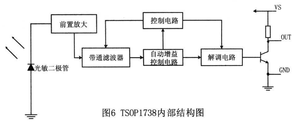
Infrared communication interface design based on Lingyang SPCEO61A 0 Introduction With the development of infrared technology, infrared communication has become an increasingly popular wireless communication method. Infrared communication uses infrared as a carrier to transmit data information. It has the advantages of intuitiveness, simple operation, high reliability, low power consumption, strong anti-interference ability, easy high-speed application, and flexible space access. Infrared communication interface is particularly widely used in handheld devices. This paper proposes a design scheme of infrared communication interface based on SPCE061A of Lingyang company, and has the following functions: a. The communication distance is greater than 5m; b. The transmission rate is 1500b / s; c. The bit error rate is less than 0.5%. The receiving circuit is composed of an infrared receiving tube and an amplifying circuit. After Q4 receives the infrared signal, it performs first-stage amplification through transistor Q1. The amplified signal is sent to transistor Q3 for second-stage amplification. The amplified output can be obtained through Rx output. Infrared receiving signal, as shown in Figure 2. 2 hardware circuit design The one-chip computer that the infrared communication interface of this text uses is SPCE061A of Lingyang Company. 2. 2 hardware circuit interface circuit As shown in Fig. 4, J1 is the transmitting signal and receiving signal interface of the infrared transmitting / receiving circuit, and can be directly connected with the 10B high 8 bits of SPCE061A through the 10Pi ns cable, and output through IOB8 of SPCE061A 38kHz modulation wave, IOB8 output TImerA PWM pulse width modulation output. The carrier map is shown in Figure 3. There are two main types of infrared signal modulation, one is pulse width modulation (PWM), and the other is pulse time modulation (PPM) that achieves signal modulation through the time interval of the pulse train. The method used in this article is PPM. The working principle of TSOP1738 is as follows: First, the received infrared light signal with a carrier frequency of 38kHz is converted into an electrical signal by an infrared photosensitive element, and then amplified by a pre-amplifier and an automatic gain control circuit. Then it is filtered by a band-pass filter, and the filtered signal is demodulated by a demodulation circuit. Finally, the output stage circuit performs reverse amplification output. Use IOB2 to detect this signal. Figure 6 shows the internal structure of TSOP1738. 2.3 Software design Take a simple application of multifunctional energy meter as an example, which mainly includes two parts: the host meter reader software and the meter meter slave software. In the data exchange, the handheld unit or data terminal is the main station. The rate device (generally refers to the multifunctional energy meter) is a slave station. Both the master station and the slave station must have two sets of equipment for receiving and transmitting. The procedures for receiving and processing data are the same. Considering that the master station and the slave station cannot receive and transmit signals at the same time, the data transmission is bidirectional, the slave station needs to receive the information transmitted by the master station, and also needs to transmit the information to the master station. With the receiving equipment, if the full-duplex communication method is adopted, the signal transmitted by itself may be received by itself, so the half-duplex communication serial method is adopted. Here take the receiving and transmitting part of the master station as an example to illustrate the software design and flow chart of each part. 2.3.1 Software Design of Infrared Transmitting Part The transmitting part starts with the start bit of the sync header, and then transmits the 8-bit data segment, as shown in Figure 7. At the transmitting end, the CPU continuously scans the keyboard, and once it is found that a key is pressed, the transmitting subroutine is enabled to transmit the corresponding value.
LED wash wall lamp, as the name implies, let the light like water wash the wall, mainly used for building decoration lighting, and also used to outline the large buildings.Since LED has the characteristics of energy saving, high luminous efficiency, rich color and long life, the washing wall lamp of other light sources is gradually replaced by LED washing wall lamp in 2013.
Product size
Technical parameters
1. Main material:High - pressure cast aluminum, high - light ultra - white tempered glass, back flame retardant ABS;
2. Surface treatment:UV Polyester powder coating;
3. The light body color:Dark grey;
4. Safeguard procedures:Silica gel ring compacted waterproof;
5. Average lifetime:350mA20000hours,500mA15000hours;
6. Control mode:CC/DMX512;
7. Operating ambient temperature:-25℃~50℃
8. The light colored temperature: Red/Green/Yellow/Amber/Vermilion/Acid blue/3000K/4000K/5000K/6000K
9. Light distribution device:Optical lens series:8°/15°/25°/45°/10×30°/10×60°/20×40°
10. Working voltage:DC24V
11. Way to install:Single U/Double U Adjustable Angle bracket
12. Level of protection:IP65
13. Working environment humidity:10%~90%
Led Wall Washer Lamp,Led Wall Washer Light Fixtures,Led Wall Washer Flood Light ,Led Wall Washer Light Products Jiangsu chengxu Electric Group Co., Ltd , https://www.satislighting.com
1 The principle of infrared communication Infrared communication uses the 950nm near-infrared band as an information carrier to achieve short-distance confidential communication and information forwarding between two points. The basic principle of infrared communication is that the sending end modulates a binary signal to a certain frequency. Pulse sequence, the signal is emitted in the form of light pulses by driving the LED, and the receiving end uses photodiodes to convert the received light pulses into electrical signals, which are then processed by amplification, filtering, etc. and sent to the demodulation circuit for demodulation and restoration For the output of binary digital signals, the infrared emitting part modulates an infrared radiation source to emit infrared signals, and the receiving part uses optical devices and infrared detectors to receive.
The infrared emission circuit is composed of resistor R2, transistor Q2, resistor R3 and infrared emitting diode D1, as shown in Figure 1. 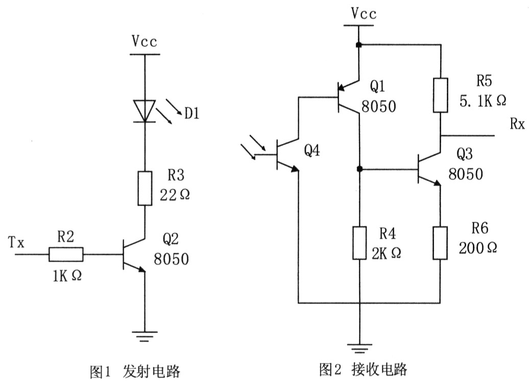
2.1 Performance of SPCE061 A SPCE061A is a 16-bit microcontroller with high cost performance produced by Lingyang Company. Its operating voltage range is 2.6 ~ 3.6V, and its operating frequency range is 0.320 ~ 49.152MHz. When the working frequency is set at 49.152MHz, the instruction cycle is about 20ns. SPCE061A single-chip microcomputer adopts a modular structure, with 16-bit microcontroller as the core. SPCE061A microcontroller has built-in 2k word SRAM; built-in 32k FLASH; programmable audio processing; crystal oscillator 2 16-bit programmable timers / counters (the initial count value can be automatically preset); 2 10-bit DAC (digital-to-analog conversion) ) Output channel; 32-bit universal programmable input / output port; 14 interrupt sources can come from timer A / B, time base, 2 external clock source inputs, key wake-up; with touch-key wake-up function; use Lingyang audio Encoding SACM S240 mode (2.4kb / s), capable of accommodating 210s of voice data; phase-locked loop PLL oscillator provides system clock signal; 32768Hz real-time clock; 7-channel 1O-bit voltage analog-to-digital converter (ADC) and single channel Sound ADC; sound ADC input channel built-in microphone amplifier and automatic gain control (AGC) function; with serial device interface; with low voltage reset (LVR) function and low voltage monitoring (LVD) function; built-in online simulation circuit ICE (In- Circuit Emulator) interface; with confidentiality capability; with watchdog function.
Its unique voice function can be used in many aspects. This single-chip microcomputer used in infrared communication interface can automatically broadcast voice and has a unique style. In this infrared communication interface design, the input and output ports play an important role. 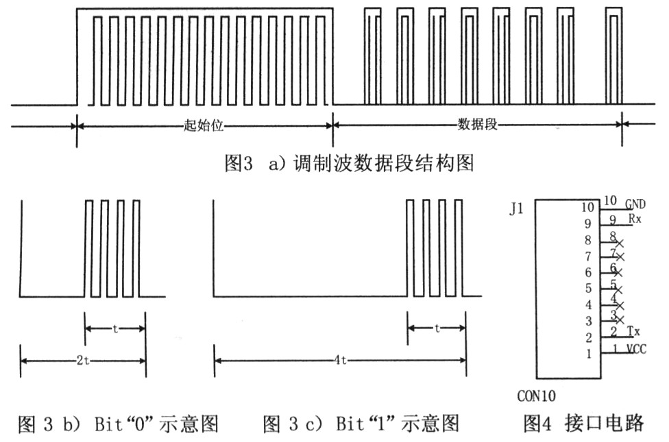
The 61 board is the control core of this system. The infrared emission tube is TSAL6238 produced by Visay company, which is used to emit an infrared beam of 940nm. The emission circuit is mainly composed of a resistor-capacitor transistor and an infrared emission tube. The serial code is mainly sent by TImerA timer, IOB8 programming as the second function is controlled by TImerA output pulse width modulation signal APWM0 with adjustable duty cycle to generate a 38kHz carrier signal, as shown in Figure 5 is a 38kHz modulated wave. Serial data is sent by the serial output terminal TXD of the single-chip microcomputer and drives the triode, and two infrared transmitting tubes are used to send the 38kHz carrier signal to the outside in the form of light pulses. When the serial code is 1, the output is turned on, and when it is 0, the APWM0 output is turned off (output low level). Use TImerB to control the pulse width. The external receiving circuit selects the special infrared receiving module TSOP1738 produced by Vishay. The receiving module is a three-terminal component, using a single power supply + 5V power supply, with low power consumption, strong anti-interference ability, high input sensitivity, and insensitivity to infrared light at other wavelengths (other than 950nm). Its internal structure block diagram is as follows Figure 5 shows. 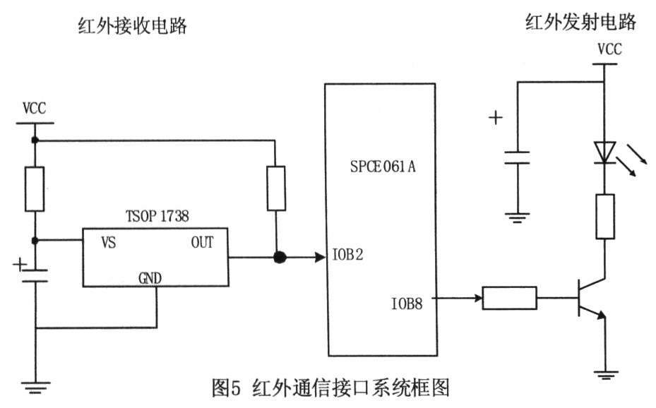
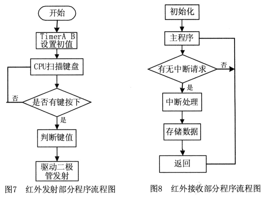
2.3.2 Software design of the infrared receiving part The infrared receiving part mainly receives data through the infrared receiving module TSOP1738. This part of the program is relatively simple. The interruption is used to make the system enter the state of receiving data and store the data in the data of the 61 board. In the memory, this completes a receiving process.
3 Conclusion The computer infrared communication interface circuit introduced in this paper has the advantages of simple circuit, low cost, convenient programming, easy maintenance and high reliability. This infrared communication interface is designed for infrared meter reading system. The system consists of an electric energy meter with infrared communication function (installed at the user end), a handheld meter reading instrument and a computer. When you need to understand the power consumption of the user terminal, use the handheld meter reading instrument to obtain the user number and power consumption by using the infrared communication function outdoors. Then use the infrared communication function between the hand-held meter reading instrument and the computer to input the user number and power consumption into the computer, and the computer calculates the power consumption of a user based on the user number for the current month, last month, and this year. The innovative point of the author of this article is that this system has a good work, and has the advantages of speed, accuracy and convenient maintenance compared with manual meter reading. With the expansion of the electric energy meter function, the infrared interface is playing an increasing role in function setting, automatic meter reading, timely data collection, etc., and has a good application prospect. 

May 28, 2020