Car audio power amplifier circuit This article introduces a kind of best and interesting high-quality audio power amplifier structure scheme for automobiles, which can be realized with the lowest cost, and this scheme can also be used in small portable music centers. The characteristic of this power amplifier is that there is no additional amplifier added to the low channel. The speaker of the low frequency channel is connected to the output of the two stereo channels through the filter, and one of the signals is inverted, thus forming a bridge connection circuit. In the case of low voltage power supply Next, enough power can be obtained on the compression type low frequency public speaker. The audio power amplifier circuit is shown in Figure 1. The dual amplifier IC1 LM358 constitutes a preamplifier. Half of it works in the inverting state on the left channel, while the other half works in the inphase state on the right channel. The multiple is equal to 1, in addition to inverting the signal in one of the channels, it also provides the bias voltage at the input of the power amplifier IC2 and IC3 integrated circuit TDA2030. In order to make the output voltage of the power amplifier amplifier increase steadily and slowly after the power supply voltage is turned on, to eliminate the "click" sound generated when the power is turned on, the "click" sound circuit R6 and C5 are introduced into the circuit. At that time, the voltage on C5 increases slowly, and does not make the output click. Diode VD2 is used for the rapid discharge of capacitor C5 after the power is disconnected, and voltage regulator VD1 is used for the DC voltage at the output of the power amplifier. Therefore, the fluctuation of the power supply loop will not affect the quality of audio playback. Another feature of this circuit is that it can work in an ordinary single-channel state, such as listening to language programs. In this case, the power consumption is reduced and the lower limit frequency of the amplified signal is increased. At the same time, the switch SA1 is used to disconnect the speaker BL3 and the filter, and the speakers BL1 and BL2 are connected via capacitors C16 and C17, which attenuates signals with frequencies lower than 100 Hz to 150 Hz. The BL1 and BL2 speakers are also connected via R17, C14 and R18, C15 to pass signals with frequencies higher than 300 Hz. The parameters of the audio power amplifier are as follows: (1) The rated range of the audio frequency (-3dB level) is 25 ~ 22000HZ; (2) The effective power of the stereo channel is 5.5W × 2; (3) The effective power of the low channel is 22W; (4) Rated input voltage 0.25V; (5) The harmonic coefficient is 0.12% at the rated input voltage; (6) The voltage amplification factor is 26dB; (7) Quiescent current 120mA ~ 150mA; (8) The power supply voltage is 11.7 to 14.4V. The biggest feature of this audio power amplifier is its connection method. This connection method is by means of two electromagnetic relays K1 and K2. When the power is applied to the "K" terminal, the two relays are connected through capacitors C22 and C23. After the capacitor is charged, the relay winding is connected in series through the diode VD3, which can reduce the current consumption through the relay winding and improve the temperature condition of the power amplifier. Component selection and installation: The inductance L1 is self-made, and the iron core of the output transformer of the portable radio is used, and the skeleton is wrapped with 1.0mm to 1.2mm enameled wire. The inductors L2 and L3 are air-core coils, which are wound with 100 turns of enameled wire with a cross-sectional area of ​​about 1 mm2 on a wooden pattern plastic mold with a diameter of 50 mm. The adjustment of the power amplifier is to first determine that the quiescent current of the amplifier does not exceed 150 to 200 mA. No voltage is applied to the relays K1 and K2, and their contacts K1.1 and K2.1 are short-circuited with a short-circuit wire, and an ammeter is connected in series with the fuse FU1 to measure its quiescent current. Apply voltage to the relays K1 and K2 (remove the short-circuit wires of K1.1 and K2.1), turn on the voltage circuit, and close the contacts of K1.1 and K2.1. Switch SA1 is in the position shown in the figure, add a music signal to the input end of the amplifier, and select resistors R17 and R18 to equalize the volume between the low-frequency and mid-high frequency networks. Adjusting R11 and R12 can change the amplification factor of the amplifier, and adjusting C5 can change the growth time of the DC voltage at the output of the amplifier.
Our Led Shoebox Light is designed to replace 100W to 1000W Metal Halide and High Pressure Sodium shoebox lights in parking lots and other public areas. China LED Area Lights Manufacturer Supplier. Led Shoebox has 3 Step Dimming(20% / 50% / 75% / 100% wireless remote control) & perfect for parking lots, roadways, car dealerships, campuses, parks, and as a replacement for street lights and vapor lamps. This Led Shoebox Fixture is available in 100w,150w,180w,200w and 320w. Photocell sensor and motion sensor is acceptable.
Led Shoebox Light Led Shoebox,Led Shoebox Light,Led Shoebox Fixture,Shoebox Light Shenzhen Bbier Lighting Co., Ltd , https://www.chinabbier.com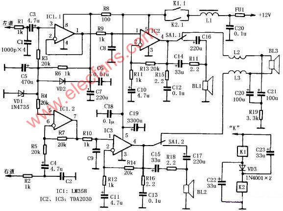

May 27, 2020