Increased efficiency in motor design
In recent years, the demand for energy saving in household appliances has become more and more intense. It is obvious that only the refrigerator consumes more than 10% of the household electricity. Since the motor of the refrigerator is mainly operated at a low speed, there is a great energy saving potential, which can be achieved by simply improving the driving efficiency of the motor in the low speed drive.
This article refers to the address: http://
Similarly, it is estimated that 65% of industrial electricity is consumed by electric drive motors, and there is no doubt that businesses are realizing that energy efficiency will be the key to improving yields and competitiveness. There are two main ways to reduce energy consumption in an electric drive motor: improving the efficiency of the motor itself and using an adjustable speed drive to effectively control its operating speed. The two methods are described below.
The use of variable frequency drive motors has been around for nearly 100 years, and newer applications now use more efficient, simple and lightweight motors, including brushless DC motor series and magnetoresistive switching motor series. Both the brushless DC motor and the reluctance switching motor use an MCU or DSP to synthesize the drive signal and then use a MOSFET or IGBT device as a power switch for amplification.
The increase in energy costs is prompting renewed interest in brushless DC motors with variable frequency drives. These highly efficient and versatile motors have high torque-to-weight ratios, but the main factors that hinder their widespread use are the high cost and complexity of the drive circuit.
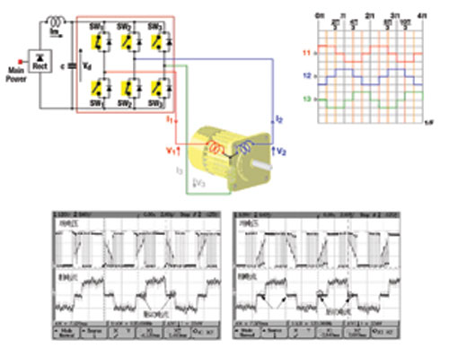
There are several different ways to design a variable frequency drive. The most popular low-frequency driving method for conventional three-phase motors is the trapezoidal wave drive (see Figure 1).

Figure 1 Trapezoidal wave control and measured waveform
If higher efficiency and performance are required, a sine wave must be generated by a pulse width modulation (PWM) method. To further improve efficiency, a spatial vector modulation method can also be used.
There are two main types of three-phase synchronous motors with permanent magnets: sinusoidal pulse modulation (PM) synchronous motors and trapezoidal brushless DC motors. The two are identical in many respects (for example, both are electronically commutated), but there are two main differences.
â— The structure of the motor The sinusoidal control waveform motor has a different shape from the BEMF induced voltage of the trapezoidal control waveform motor.
â— The control mode controls the voltage waveforms differently, which are three-phase sinusoidal waveforms (all three phases are simultaneously turned on) and rectangular six-step commutation (any phase is not connected at any time).
Sinusoidal pulse modulation (PM) synchronous motors are becoming increasingly popular, replacing brushed DC conventional motors and other types of motors in a wide variety of applications. The main reason is that it provides better reliability without the need for brushes, as well as higher efficiency, lower noise and other advantages (as shown in Figure 2).

Figure 2 Block diagram of the built-in permanent magnet synchronous motor (IPMSM) vector control system Intelligent power module With the design of miniaturized motors easier, the intelligent power module (SPM) provides a power interface with the MCU or DSP. The main advantage of these modules over discrete component solutions is reduced parasitic self-inductance and higher reliability, since all switching devices in the module use the same type of substrate. Therefore, they have the same characteristics and good testability.
SPM is a driver circuit that can be directly connected to the microcontroller's low voltage TTL or CMOS output pins, as well as other protection circuits. The module has a temperature sensor to monitor the temperature of the node, and corresponding control logic to prevent accidental opening of the high-side and low-side switches, dead-band control, and waveform shaping circuitry to reduce EMI. The driver ICs of these modules can be optimized for switching power devices to reduce EMI and drive losses.
The high-voltage bridge driver's compact, low-power module revolutionizes the high-voltage (600V) bridge drive for motor drives. These drivers are designed to reduce parasitic drain-source capacitance in internal high voltage integrated circuit processes, so they can operate stably with standard negative voltages above -9V.
The positive and negative peaks of the supply voltage do not lock the driver and lose gate control. In the last decade or so, the gate driver has changed a lot. If the transmission delay is less than 50ns, the switching frequency can be as high as 100 or 150kHz.
The common-mode dv/dt noise absorbing circuit inside the integrated circuit helps to reduce the possibility of false opening and makes the power circuit more stable, and can make the volume more compact without the need for additional filtering circuits. Modern integrated circuits with low quiescent current, such as the FAN7382 and FAN7384, can reduce operating temperature rise and thus increase reliability.
Another big advantage is the reduced board area and cost, which replaces the four isolated power and optocoupler isolation circuits between the microcontroller PCB and the power switch PCB, which was in the previous generation of motor driver products. It is very common.
IGBT: Comparison of NPT and PT For more than two decades, the power switching device in the motor driver has been an IGBT, which can reduce losses at a certain switching frequency. In the field of motor drives, this also indicates that the IGBT series is driven at a frequency of approximately 5 kHz for consumer motors, many industrial motors have a drive frequency of approximately 29 kHz, and some motor-driven drives have higher drive frequencies.
IGBTs continue to innovate, and the turn-on voltage and turn-off energy in each switching cycle are strongly related to the reliability and low cost of the module. In the last five years, the capabilities of conventional IGBTs have been greatly improved, and emerging non-breakdown IGBTs have become more popular. The NPT IGBT that looks very much like a conventional breakdown IGBT is manufactured by a different process from the past. Unlike MOSFETs and conventional IGBTs, NPT IGBTs are filled with P regions and underlying metal regions in the wafer process.
The turn-on voltage Vce(sat) of an NPT IGBT is generally not as high as, or at least as low as, a conventional IGBT. However, they are usually more stable. The ability to withstand long periods of short circuit or overcurrent conditions makes them very popular in the field of motor control. In addition, if the switching waveforms of the two types of IGBTs are compared, it can be found that the EMI generated by the NPT IGBT is much lower than that of the PT IGBT.
NPT IGBTs have a falling time that is essentially a single slope. In other words, the fall time of a conventional IGBT consists of a very high dI/dt region followed by a very long wake. In the latter region, the rate of current drop is very low and the device losses are very high. In the high dI/dt region, the EMI generated by the conventional IGBT is very high, and usually has the possibility of affecting the driving circuit, and the driving circuit and the power switching tube must be isolated. Another advantage of the NPT IGBT is that it can be fabricated using a process where Vce(sat) is a positive temperature coefficient, which is a very important parameter when paralleling IGBTs.
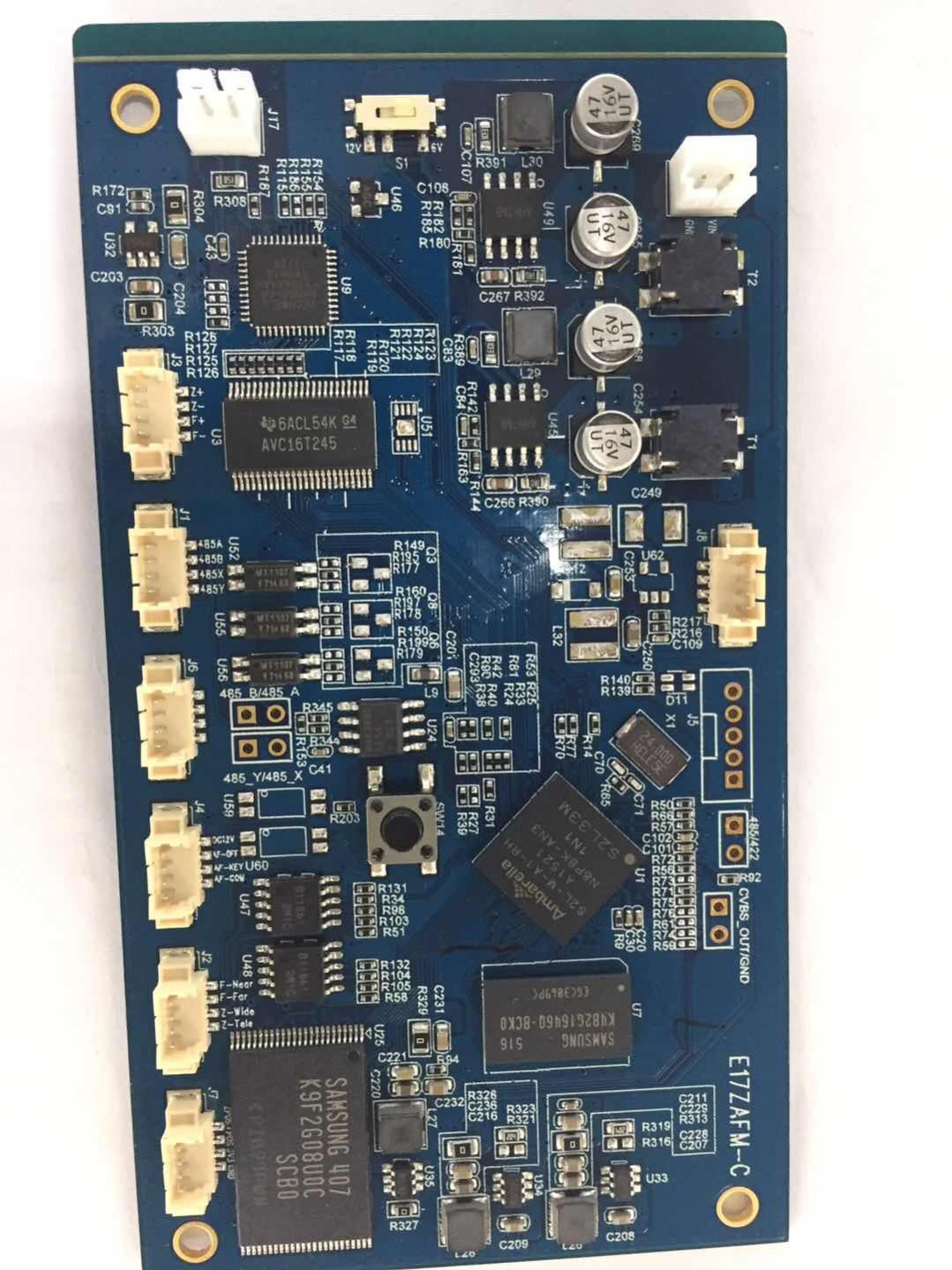
Printed Circuit Board assembly sometimes called PCB Assembly(PCBA).
The bare board is populated with Electronic Components to form a functional. In through-hole technology, the component leads are inserted in holes surrounded by conductive pads; the holes keep the components in place. In surface-mount technology (SMT), the component is placed on the PCB so that the pins line up with the conductive pads or lands on the surfaces of the PCB; solder paste, which was previously applied to the pads, holds the components in place temporarily; if surface-mount components are applied to both sides of the board, the bottom-side components are glued to the board. In both through hole and Surface Mount, the components are then soldered; once cooled and solidified, the solder holds the components in place permanently and electrically connects them to the board.

PCB Assembly
PCB Assembly,PCB Circuit Board ,Electronic PCB Assembly,Professional PCB Assembly
Orilind Limited Company , http://www.orilind.com