With the increase of multimedia devices in automobiles, such as CD/DVD players, digital TVs, etc., the in-vehicle network connecting these devices includes: Bluetooth, CAN, D2B, FireWire, MOST, Mobile Media Link (MML), LIN and ZigBee. Etc., this article introduces a Bluetooth-based architecture for remote diagnostic interface that allows test engineers to monitor and operate the vehicle's sensors and control units to complete test tasks, whether in the vehicle or at any location outside the vehicle. . This article refers to the address: http:// Network software structure
The positive active material is mainly made of nickel, and the negative active material is mainly an alkaline battery made of hydrogen storage alloy.Nickel-metal hydride (nimh) batteries are modified from nickel-cadmium (nicd) batteries, which offer higher capacitance, less obvious memory effects, and lower environmental pollution at the same price.The special charger can be used for quick charging in one hour. The self-discharge characteristic is better than nickel-cadmium battery, which can be retained for a longer time after charging and can be repeated for more than 500 times.
The charger adopts high frequency switching rectifier power-supply module. The working process of the charger is controlled by microprocessor in real-time, automatic power on/off, simple operation, safe and reliable. The user can view the operation parameters and working status through the touch screen.
Nimh Battery Charger,Industrial Battery Charger,Substation Battery Charger,Nimh Battery Pack Charger Xinxiang Taihang Jiaxin Electric Tech Co., Ltd , https://www.agvchargers.com
The future remote diagnostic system will provide an unprecedented access to the car's power controller, whether it is in a repair shop or on the road. Wireless technologies such as Bluetooth provide the features needed for short-range wireless communication between the car's technician's laptop and the in-vehicle network, allowing technicians to monitor and operate the car, anywhere in or out of the car. Sensor and control unit.
From the perspective of automotive technicians, the front end of the network is a Telematics Control Unit (TCU) that connects the various networks interconnected with the Integrated Networked Vehicle (INV). There is a clear trend in the automotive industry to develop a centralized service gateway model for INV, and Bluetooth technology provides a connectivity solution for many links in the network. It complements the existing CAN (Controller Area Network) bus by providing wireless connectivity and hoc networking. Other communication media also have their own advantages, such as MOST (Media-Oriented System Transport) and IEEE 1394, which provide high-bandwidth audio/video communications for consumer electronics and entertainment systems.
This new technology uses the CAN bus to achieve highly reliable communication between systems that have an impact on vehicle performance and safety. High-speed CAN networks are used to connect engine control units (ECUs), anti-lock brake systems (ABS), and other critical systems. Low-speed CAN networks are often used to implement multiple connections. In this network, multi-lamp illuminators, power windows, and power seats are all used as nodes on the CAN bus instead of using large, expensive cable bundles. Point-to-point connections to connect. 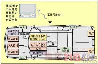
Figure 1: Network Architecture and Remote Diagnostics Interface This article describes a Bluetooth-based architecture for remote access diagnostic interfaces in which the Bluetooth networking protocol is used to provide the underlying transport (physical) medium for an HTTP-CAN gateway. . With the help of an embedded HTTP server running on the TCU, service technicians can monitor and control the various nodes on the INV from the web browser of the Bluetooth-enabled laptop. This wireless interface provides easy access and is accessible from the underbody, under the hood or in the passenger compartment. The system described in this article uses Bluetooth's Dial-Up Networking (DUN) feature to emulate an external modem to support a web browser that "dials" to the car's CAN network. By using standard communication protocols such as TCP/IP and embedding the corresponding software of the car into the HTTP server, the technician's hardware and software are fully scalable with respect to the car design, even if the car is maintained by different manufacturers, models and models. It is totally different from the repair process.
Diagnostic access to the in-vehicle network
Figure 1 shows the network architecture of an in-vehicle network accessed using a Bluetooth-based diagnostic system. A web browser on a conventional Bluetooth-enabled laptop is used to access the TCU, which provides a user interface to access the car network. By embedding the diagnostic interface in the car itself, the manufacturer can customize the description of the data and the process of submitting it to the technician. Diagnostic procedures can also be provided based on the option installation in a particular car. In addition to options selected by consumers such as air conditioners, ABS, etc., there are usually other differences in components that are invisible to consumers. For example, two to three pumps may be used in one model year. After taking all these differences into account, there may be dozens of combinations. Customizing a dedicated diagnostic interface for a specific car reduces the likelihood of technicians getting lost and using incorrect diagnostics.
This interface can be used to access real-time operational data during vehicle travel and historical data from the controller and to log logs of unusual events such as engine ignition failures, overtravel sensor data, etc. The controller can also be used to control automotive sensors for testing, such as verifying that the injection control device is properly responsive to sensor inputs.
The diagnostic system also recovers data for the car manufacturer to develop an indicator model before the failure. Learning algorithms can be used to optimize automated diagnostic tools by uploading data logs from flash memory and correlating them with fault reports provided by technicians. Maintenance and repair equipment provides this information to assist in the diagnosis of the vehicle. When diagnosing problems in a car, the first step should be to upload flash data, because the cost of hiring a skilled technician is expensive, and using the car manufacturer's software tools can often diagnose the problem (or provide useful advice) ).
Internet model
Since the system requires networks with different reliability and bandwidth, future in-vehicle networks will use multiple network types. The layered protocol and central gateway processor combine to enable transparent communication between different networking technologies.
Along with the revolution that is taking place in the structure of automotive electronics, many emerging networks have emerged. Multimedia devices in automobiles, such as CD/DVD players, digital televisions, etc., require networks with large synchronous bandwidth; others require wireless networks or other configurations. To meet the demand for these broad and growing automotive network applications, researchers are developing many proprietary network protocols. Future in-vehicle networks are likely to include:
Bluetooth piconet: A medium-bandwidth wireless network that has become the standard for communication with cellular phones and portable computers.
CAN network: A medium-bandwidth, high-reliability wired network is already the standard in the automotive industry.
Audio/Video Network: A high-bandwidth wired network for entertainment media. There are currently several competing protocols in this application area, including internal data bus (D2B), FireWire (IEEE 1394), Media Oriented System Transport (MOST), and Mobile Media Link (MML).
Low-overhead wired networks: UART-based wired networks (LIN) and chip-to-chip buses, such as I2C, SPI, and Microwire, support low-cost interfaces to keypads, displays, and sensors.
Low-overhead wireless networks: Low-bandwidth wireless networks based on ZigBee or private networks, RF remote keys for tire pressure sensors, alarms and door locks, and other applications that require a wireless interface and lowest cost.
Future in-vehicle networks typically include multiple CAN networks: low-speed networks for door locks, taillights, and more, which reduce traces; high-speed networks for critical high-performance functions such as power control. In the 7 series BMW, three CAN networks are used. Among them, the CAN power network and the CAN body network are connected to the central gateway module, which in turn is connected to the Byteflight star network. The Byteflight star connector is a safety critical control and information module. The third CAN network connects the CAS (car access system) to the gating unit and the seat control unit (up to 11 units). The CAS also provides an interface to the CAN body network, which includes up to 20 nodes.
The software structure of the TCU and remote diagnostic system is shown in Figure 2. 
Figure 2: Software Structure of the TCU and Diagnostic System The diagnostic system runs a generic web browser to view the information provided by the web server on the TCU. By executing a web server on the TCU, the car manufacturer can provide a diagnostic interface that can be accessed without prior knowledge of the implementation details (which may change even within the same model year).
The advanced driver in each CAN node executes an application specific protocol in response to a request received from the network server. The driver is responsible for analyzing and decoding PDUs (Protocol Data Units) and generating local tasks that meet the required behavior of the PDU. Once the local task is over, any results generated by these tasks are formatted and returned to the web server via the CAN bus.
The DNC (Dynamic Node Configuration) server maintains a list of active nodes. When a node is added (which can be "hot add" or "cold add") to the CAN network, it immediately begins broadcasting configuration requests to the DNC server running on the TCU. Since it is modeled using Dynamic Host Configuration Protocol (DHCP) used by many computers to automatically acquire network configurations, a similar (simplified) protocol can be utilized to allow CAN nodes to obtain certain required network configuration data. With this mechanism, nodes can be added or removed in a similar way to plug-and-play in a computer. CAN nodes use DNC requests to publish their randomly generated node ID numbers, which are intended to be used as aliases for their names or "addresses" on the CAN network (do not use them with message-based filtering or IDs used on CAN networks). No. confused).
When the DCU's DNC server receives a DNC request, it first checks that the ID number requested by the node is valid and does not conflict with any other node on the current network. The server then checks that it has enough storage to add the node's configuration table to its list of active nodes. Finally, if the above check passes, the DNC server will accept the request and assign the node a unique number as the name during its activity. At the same time, the ID number of the node will also be added to the server's active node list. All future communications to this node will use this protocol ID. If the requested ID number is invalid, the TCU will reject the request, prompting the node to request another ID number until the ID number is acceptable.
The TCU acts as the host for the CAN network because the CAN node itself does not run a TCP/IP based protocol stack. When a web browser needs to access a CAN node, it communicates with the web server. The web server interprets the actions requested by the browser and generates communications on the CAN network to perform the action.
An example of a TCU processor is National Semiconductor's CP3BT26, which is part of the CP3000 series of connectivity processors. It has the following characteristics:
24MHz 16-bit RISC CPU with 32-bit extensions;
256K bytes of on-chip flash memory;
8K bytes of data flash (writable when executed from 256K flash);
32K bytes of static memory;
Bluetooth baseband controller;
Dual CAN 2.0B active controller with target storage (called fullCAN);
USB 1.1 full speed node;
ACCESS.bus, SPI, Microwire/Plus low overhead chip-chip bus;
Four UART;
AAI codec interface (compatible with SSI interface);
8-channel 12-bit AD converter;
54 general purpose I/O port pins;
General purpose timer
Watchdog timer
Low voltage mode
The device features a full Bluetooth and TCP/IP protocol stack that includes a suite of pre-tested software development tools, peripheral drivers and real-time operating systems.


August 09, 2019