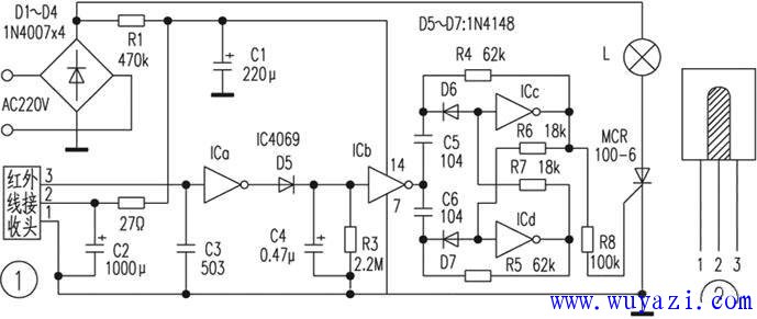
In today's homes, infrared remote controls for devices like TVs, VCDs, and VCRs are quite common. This circuit was designed with those devices in mind, allowing the remote control to be repurposed: instead of just controlling the device, it can now send infrared signals to control lighting fixtures from a distance of over 8 meters. The circuit operates based on a simple principle. As shown in Figure 1, it mainly consists of an infrared receiving head and a CMOS IC4069. When the infrared receiver is not receiving any signal, it outputs a high level. However, when it detects an infrared pulse from the remote control, the first pin of the receiver goes low, producing a pulse signal. This signal is then shaped, amplified, and inverted by ICa, resulting in a negative pulse. The pulse is then detected by D5, C4, and R3, and sent to ICb. Once the voltage at the input of ICb reaches the threshold level of the inverter, it switches to a low output. Then, as C4 discharges through R3, the input voltage drops below the threshold, causing ICb to return to a high output. Each time the infrared transmitter is pressed, a negative pulse is generated at the output of IC6, which triggers a bistable circuit made up of ICc and ICd. This causes the bistable circuit to toggle between high and low output levels. The output then controls the conduction or cutoff of a unidirectional thyristor (SCR) via R8, thereby switching the light on or off. The power supply for this circuit is obtained by rectifying and stepping down the 220V AC using D1-D4, R1, and C1, providing a stable +5V DC to the entire system. For testing and adjustment, once all components are correctly installed, you can measure the voltage at each pin of the TC4069, which should typically be around +5V. If the voltage is too low, adjust the resistance of R1 accordingly. The circuit consumes very little power, with measured consumption less than 0.5W. It's important to note that the board may still carry high voltage, so extra caution must be taken during testing to avoid electric shocks. Component selection is also crucial. The infrared receiver has a high internal DC resistance and operates at +5V (as shown in Figure 2). The SCR used should have a power rating comparable to the incandescent lamp being controlled to prevent damage due to overcurrent. Fiber Optic Patch Panel,Fiber Patch Panel,Fiber Distribution Panel,Optical Patch Panel Cixi Dani Plastic Products Co.,Ltd , https://www.danifiberoptic.com