Analysis of measurement circuit for detection circuit of lock-in amplifier with small voltage
Circuit Function
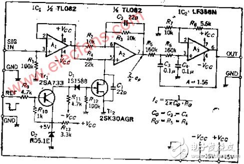
This circuit is designed for low-frequency signal detection, featuring a polarity inversion and in-phase switching mechanism. It operates at frequencies below tens of kilohertz and is suitable for applications requiring high DC stability. The design is particularly effective in the entire low-frequency range, making it ideal for precision measurements.
The analog switch used in this circuit is typically an N-channel J-FET, which offers good performance for general-purpose use. A 12 dB/OCT low-pass filter is incorporated into the smoothing circuit to reduce response time and improve signal quality. Full-wave rectification is employed in the detection process, allowing for efficient suppression of higher harmonics. This makes the circuit highly suitable for use in lock-in amplifiers, especially when measuring small voltages with high accuracy.
Working Principle
The operational amplifier A1 serves as an impedance buffer, ensuring that the input signal remains unaffected by the following stages. If the front-end stage already has a low output impedance, A1 can be omitted. A2 functions as an inverting and non-inverting amplifier, capable of switching between these modes. When TT2 is activated, the non-inverting input is grounded, and the gain becomes -1 (R3/R2).
When TT2 is turned off, the input signal is passed through R4 to A2. Due to the high input resistance, the inverting input follows the non-inverting one, effectively acting as a voltage follower. The analog switch composed of TT2 requires the gate-source voltage VGS to swing negatively to the pinch-off voltage VP. To operate with TTL levels, +5V and 0V are replaced with -VCC and +5V, or CMOS analog switches may be used instead, though cost considerations must be taken into account.
TT1 is a PNP transistor with its emitter connected to -VCC. When the input TTL level is "L", TT1 turns on, allowing current to flow through the collector, which turns off D1, resulting in ROS ≈ 0 and activating TT2. Capacitors C1 and C2 help suppress voltage spikes. When the reference signal is in phase with the input, the output of A2 is a full-wave rectified positive signal. If the signals are out of phase by 90 degrees, the output becomes a negative half-wave rectified signal. At 90° and 270°, the polarity is reversed, forming symmetric S-shaped waves. After filtering, the output becomes zero regardless of the input amplitude.
Assuming the peak input voltage is E1, the average value of full-wave rectification is approximately 0.636E1. With a filter gain of 1.56, a DC voltage close to E1 can be obtained at the output. The low-pass filter is designed using the same parameter method, with a cutoff frequency of 10 Hz and a roll-off of 12 dB/octave.
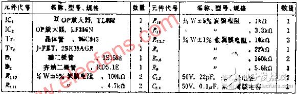
Component Selection
To ensure accurate in-phase and reverse-phase conversion, R2 and R3 must be matched precisely. The on-resistance of TT2 should ideally be zero, but in practice, it's several ohms. To minimize RON, either increase R4 or add parallel resistors. These adjustments help achieve better performance.
The level-switching circuit contains many components. For simplicity, VOB can be set to 0V, and a cut-off N-channel MOSFET or a CMOS analog switch can be used instead.
Solar connectors play a key role in solar power generation systems, and their use scenarios and performance directly affect the efficiency and reliability of the entire system.
Usage scenario:
Solar panel connection: Connectors are used to connect solar panels to ensure efficient transfer of electrical energy from the panels to the system.
Module series: A series connector is formed between multiple solar modules to form a battery string to improve the voltage and power of the system.
Inverter connection: Converts the direct current generated by the solar module into usable alternating current, and the connector plays a key bridging role in this process.
Ground installation and roof installation: suitable for different installation scenarios, such as roof installation and ground installation of solar systems.
Performance for solar power system help:
Efficient energy transmission: High-quality solar connectors minimize energy transmission losses and ensure maximum solar energy collection efficiency for the system.
Durable and reliable: Weather-resistant and corrosion-resistant connectors ensure a high degree of system reliability in all weather conditions.
Simplified maintenance: Well-designed connectors reduce system maintenance requirements and improve the long-term stability of the system.
Compliant with safety standards: Connectors that meet international safety standards help ensure safe system operation and reduce potential risks.
In short, solar connectors play a key role in improving energy conversion efficiency, ensuring system safety and reliability, and simplifying system maintenance, and selecting high-performance and reliable connectors can optimize solar power generation systems.
cable connector,dc pv connector,solar cable accessories,soalr cable connector,connector terminal
Suzhou Yonghao Cable Co.,Ltd. , https://www.yonghaocable.com