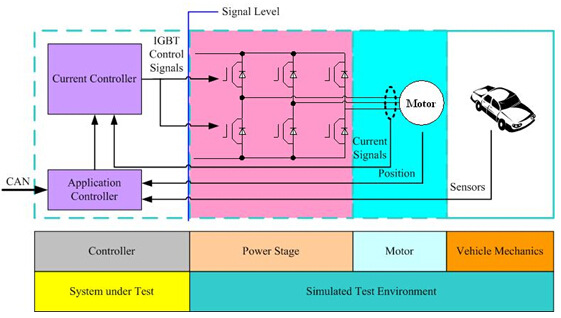
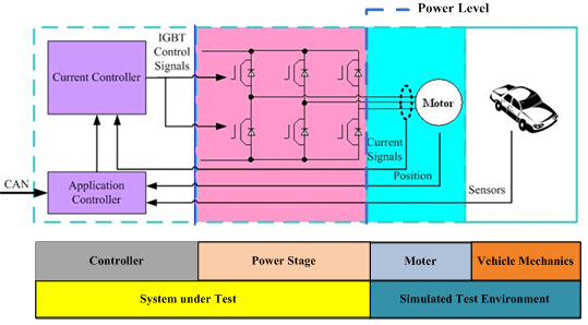
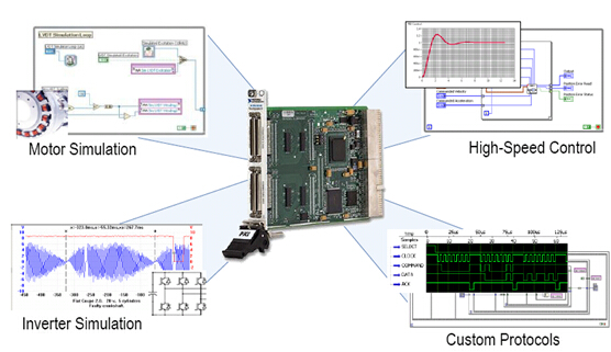
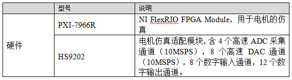
1 Overview With the continuous development of hybrid and pure electric vehicles, the complexity and reliability of motor control strategies are increasing. The demand for new energy controller development environments in automakers and suppliers is also growing. Hengrun Technology provides a total solution for new energy vehicle control, enabling engineers to verify the vehicle controller (HCU), battery management unit (BMS), motor controller (MCU), and functions in a laboratory environment. . It can simulate all the working conditions encountered in the real vehicle test, and the ECU function can be fully tested before the actual vehicle test. This article will provide solutions for testing three controllers for HCUs, MCUs, and BMSs for new energy vehicles. 2. Technical difficulties Aiming at BMS's working voltage test, single cell voltage, temperature test, SOC calculation function test, charge and discharge control test, battery heat balance test, high voltage safety function test, communication test, fault diagnosis test, etc., OEM faces many challenge. Testing BMS with a real battery pack has many drawbacks: Ø Extreme conditions simulation poses safety hazards to testers, such as overvoltage, overcurrent and overtemperature, which may cause the battery to explode. Ø SOC estimation algorithm verification takes a long time, real battery charge and discharge test takes a week or even longer. Ø It is difficult to simulate specific working conditions, such as the difference in fine SOC between battery cells during the equalization function test, and the slight temperature difference between the manufacturing unit and the battery pack during battery thermal balance test. Ø and other tests for BMS function, such as battery operating voltage, cell voltage, temperature, SOC calculation function, charge and discharge control, battery heat balance, high voltage safety function, equalization function, communication, fault diagnosis, sensor, etc. OEMs face many challenges. The MCU involves the simulation of the controlled object during the development process. The working principle of the motor body is mainly based on the principle of electromagnetic induction, and the interactive change speed of each physical quantity (such as magnetic flux, induced electromotive force, electromagnetic force, etc.) is much larger than the change of force and speed of the mechanical system. In order to ensure high simulation precision, the requirement is required. The simulation step size of the model is much smaller than the simulation step size of the general mechanical system model. Correspondingly, unlike the general electronic control system on the car, the special feature of the MCU is that it has a high control frequency and a high input signal frequency. For example, the MCU's PWM control frequency for the inverter IGBT exceeds 10 kHz; the motor's feedback motor position resolves the frequency of the signal up to 12 kHz. This requires the HIL real-time simulation system to achieve high frequency for MCU control signal acquisition and motor sensor signal simulation. Generally, the acquisition frequency reaches 1000 times of the signal frequency, and the signal simulation output frequency reaches 100 times of the signal frequency. Faced with the above challenges, Hengrun Technology provides a solution for testing new energy vehicles based on TestBase. 3. Solution 3.1. BMS solution The battery management system mostly adopts a distributed structure, including one main control unit BMU and several single detection units BCU, as shown in the following figure. Figure 3-1 Distributed management diagram of the battery management system Correspondingly, the HIL test of the battery management system can also be divided into BMS level test and BMU level test. In the BMS level test, the BMU and all BCUs are used as test objects. The HIL system needs to provide the BCU with the output voltage signal of each unit and several temperature signals. Because the BMS level test focuses on the management functions of the BMS on the battery pack itself, such as single voltage sampling, temperature sampling, SOC estimation, and unit consistency detection, it is mainly used in component level testing. In the BMU level test, the BCU adopts the form of simulation. The HIL system only needs to send the BCU related messages to the BMU through the CAN bus. It is not necessary to simulate the single voltage and temperature signals on the hardware. Part of the HIL system hardware cost. BMU-level tests are mostly used in power system or vehicle-level testing. 3.2. MCU solution The motor used in the new energy vehicle power system is generally a permanent magnet synchronous motor. The motor system is usually composed of a motor body, an inverter and an electronic control unit MCU. Tests for motor control systems can generally be divided into signal levels and power levels, the main difference being whether to connect the real inverter to the test system. Figure 3-2 Motor signal level test principle Figure 3-3 Motor power level test principle Based on the technical difficulties of MCU testing described in Chapter 2, Hengrun Technology provides a real-time simulation solution for motors based on high-performance FPGAs. NI's high-performance FPGA board PXI 7966R meets all the characteristics of real-time motor simulation, including: 1) 40 MHz PWM acquisition channel for inverter IGBT control signal acquisition; 2) 2MHz high-speed DA output channel for simulation of the resolver signal and three-phase current signal; 3) Powerful computing ability, while carrying out high-speed IO signal processing, meet the real-time simulation requirements of the motor model, the simulation step size can be less than 2us. Figure 3-4 FPGA-based motor simulation solution The configuration related to the MCU HIL test in this solution (except the general HIL system software and hardware configuration) includes: While meeting the basic test requirements of the MCU, the MCU test solution can also provide simulation functions for a variety of controlled object faults, including: Ø It can simulate the steady state and transient electrical characteristics of the motor under three-phase active short circuit and active open circuit conditions. Ø It can simulate the characteristics of rotor permanent magnet demagnetization and demagnetization. Ø It can simulate the fault characteristics of the motor windings in the same phase and phase and short circuit and open circuit. Ø It can simulate the influence of poor heat dissipation of the motor on the temperature rise characteristics of the motor. Ø Can simulate various faults of various sensors (short circuit, open circuit and other failure modes) 3.3. HCU Solution In the HCU test solution, the simulator needs to simulate the sensors required by the HCU such as: accelerator pedal, brake pedal, etc., while collecting the output signals of the HCU such as: cooling fan, front clutch and so on. The complex control functions of the HCU are generally implemented by working in conjunction with relevant controller nodes such as BMS and MCU. 4. Summary Compared with the MCU test of real battery BMS and real motor, the HIL test using battery and motor simulation technology has the following obvious advantages: Ø Safety and energy saving: avoid using high-power charging and discharging equipment, avoiding the safety hazards caused by testing to test personnel; Ø It is convenient to manufacture various BMS and MCU faults, so as to comprehensively test the BMS and MCU diagnostic functions; Ø Realize various types of battery pack (single number, voltage level) simulation and motor simulation through software and hardware configuration; Ø Quickly modify battery status, such as SOC and temperature, to improve test efficiency; Ø Simulation of battery aging and monomer inconsistency can be achieved by modifying the model parameters; Ø It can simulate the running environment of the whole vehicle. Led Linear High Bay Light,Led Tri-Proof Lighting,Aluminum Linear High bay Light,Led High Bay Light Shenzhen Ri Yue Guang Hua Technology Co., Ltd. , https://www.ledlightinside.com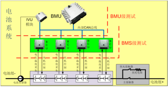
December 02, 2020