What is carrier aggregation? Carrier aggregation, as its name suggests, is to aggregate multiple carriers together to form a carrier set to serve a terminal (such as a smart phone), which is used to improve the uplink and downlink transmission rate of a single terminal. The biggest advantage is that without changing the previous physical layer structure, the bandwidth of a single terminal can be greatly increased to achieve an absolute rate increase. LTE-Advanced has taken a look at the characteristics of carrier aggregation. It is an important technology in Release 10. It mainly improves the media intervening layer (MAC) and physical layer protocol, and its maximum channel bandwidth is 20MHz from LTE itself. Upgrade to 100MHz of LTE-A to increase the data rate to 1Gbps downstream / 500Mbps upstream; and achieve backward compatibility. Screw Terminal Connector,Pcb Screw Terminal,Screw Terminal Block Connector,Screw Type Terminal Blocks Cixi Xinke Electronic Technology Co., Ltd. , https://www.cxxinke.com
Starting from Rel10, the carrier aggregation defined by LTE-Advanced is based on the R8/R9 carrier, which is fully backward compatible, so the terminal of the R8/R9 terminal can also be fully used for the system supporting carrier aggregation. For the aggregated large carrier, each of these carriers is called a component carrier (CC). The bandwidth of each component carrier may be any one of LTE supported bandwidths (eg, 1.4M, 3M, 5M, 10M, 15M, 20M). LTE-Advanced can support up to five carriers together; this is why the maximum channel bandwidth of LTE-Advanced is 100M. Carrier aggregation can be used for both FDD systems and TDD systems; and component carriers (CC) for uplink and downlink can be configured. Generally, the number of uplink CCs of the FDD is equal to or smaller than the downlink CC; while the TDD system has the same number of uplink and downlink CCs due to the uplink and downlink shared spectrum. 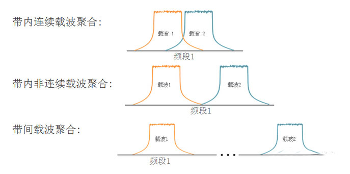
Carrier aggregation can be divided into two types, namely continuous component carrier aggregation and discontinuous component carrier aggregation. On the basis of LTE-A, it is divided into three categories: continuous carrier aggregation, in-band non-continuous carrier aggregation and out-of-band discontinuous carrier aggregation. Among them, in-band continuous carrier aggregation is the easiest in technology, but it is often difficult to achieve in the actual field due to the limitation of spectrum resources. Therefore, discontinuous carrier aggregation is a relatively flexible choice. In order to distinguish the capabilities of different mobile phones, the specification introduces the concept of CA Bandwidth, that is, different levels can not only support different numbers of CCs, but also the largest resource blocks (RBs) that can be supported in each CC. It is also different, that is, defines the maximum bandwidth that can be supported in each CC (this parameter is both Aggregated Transmission Bandwidth Configuration, abbreviated as ATBC). For the sake of complexity and practicality, there are three levels defined in the current specification (Release12):
l Level A: ATBC ≤ 100RB, CC is 1
l Level B: ATBC ≤ 100RB, CC maximum 2
l Level C: 100 "ATBC ≤ 200, CC maximum 2
Here we will also be clear, the current maximum bandwidth supported by CC will be 40M after the aggregation of two CCs. But although it is not clear, the specification has explicitly introduced a higher level of D/E/F, which will support 100 bandwidths after up to 5 CC aggregations.
The introduction of carrier aggregation test CA poses a great challenge to the rate increase of LTE-A, so what will its impact on the test be? For R&D, the R&D department will have to perform complex tests due to certain changes in the MAC layer and physical layer protocols brought by CA. What about production? We know that CA has nothing to change in the physical layer and LTE. It is nothing more than an increase in carrier (in-band or out-of-band). Therefore, we can ensure that the device under test (mobile phone, etc.) can work normally when it is multi-carrier. . So in the process of testing, we only need to ensure that the test instrument can generate the corresponding multi-carrier signal (currently two) to test it; so we need to have multiple (currently 2) signal sources to generate the band. The internal carrier or inter-band carrier can be used, which can completely simulate the actual application scenario (as shown in Figure 2 below). 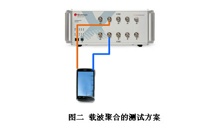
Compared with R&D testing, CA's impact on production testing has become very small; the main reason is that production testing is mainly concerned with physical layer indicators (RF parameters), while CA has no change in the physical layer, Shenzhen we can Think of it as a simple overlay.
Conclusion CA REFERENCE LTE smooth transition can be made to the LTE-A, greatly improving the downlink rate while the user to improve the user experience. In the era when we shouted Internet+, CA did not intend to take our mobile communication highway to the next level, which greatly facilitated our lives.
3 times
Window._bd_share_config = { "common": { "bdSnsKey": {}, "bdText": "", "bdMini": "2", "bdMiniList": false, "bdPic": "", "bdStyle": " 0", "bdSize": "24" }, "share": {}, "image": { "viewList": ["qzone", "tsina", "tqq", "renren", "weixin"], "viewText": "Share to:", "viewSize": "16" }, "selectShare": { "bdContainerClass": null, "bdSelectMiniList": ["qzone", "tsina", "tqq", "renren" , "weixin"] } }; with (document) 0[(getElementsByTagName('head')[0] || body).appendChild(createElement('script')).src = 'http://bdimg.share. Baidu.com/static/api/js/share.js?v=89860593.js?cdnversion=' + ~(-new Date() / 36e5)];
December 19, 2020