NPN transistors operate by having the collector current (IC) controlled by the base current (IB), with the current flowing from the collector to the emitter. In normal amplification mode, the emitter has the lowest voltage, and the collector has the highest, meaning VC > VB > VE. In contrast, PNP transistors have the collector current (IC) controlled by the base current (IB), but the current flows from the emitter to the collector. During normal amplification, the emitter has the highest voltage, and the collector has the lowest, so VC < VB < VE. In summary, the base voltage (VB) is typically in the middle, while the collector (VC) and emitter (VE) are on either side. This matches the standard BJT symbol, which can help with visualization and memory. Although BJTs aren't purely resistive, the direction of current flow aligns with the voltage polarity, and there’s no case where current flows from a low potential to a high one. Modern circuit diagrams often use a convention where the positive supply is placed at the top and the negative supply at the bottom, commonly referred to as “upside-down†or “positive under negative.†In an NPN circuit, the emitter is usually connected to ground (directly or through other components), while the collector is connected to the positive supply. For a PNP circuit, it's the opposite: the collector connects to ground, and the emitter connects to the positive supply. This arrangement ensures the correct voltage relationships between VC and VE. To convert an NPN circuit into a PNP version, you can apply the “up-down symmetric exchange†method. As long as the six key polar relationships—four current directions and two voltage inequalities—are maintained, the BJT should function properly. However, for stable operation, additional quantitative conditions must also be satisfied, known as the “biasing†or “operating point†requirements. In the common-emitter configuration, the emitter acts as a reference point, and by adjusting the base voltage (VB), you control the base-emitter voltage (VBE = VB - VE), which in turn controls the base current (IB) and the collector current (IC). The collector is connected to a higher voltage, allowing current to flow into it, like water flowing into a funnel. For the common-base configuration, the base is treated as a fixed reference, and the emitter voltage (VE) is adjusted to control VBE, which affects IB and IC. If the output needs to be a voltage rather than a current, a resistor (RC) is placed at the collector to convert the collector current (IC) into a voltage (IC × RC). To ensure VC > VE, this resistor is connected to the positive power supply, not ground. From the transistor’s perspective, both common-emitter and common-base configurations are similar—they both rely on controlling the base-emitter junction. The difference lies in whether VE or VB is fixed, depending on the configuration. In the common-emitter setup, there isn’t a fixed reference point. Instead, small changes in VBE lead to larger changes in IC or IE, causing the emitter voltage (VE) to follow the base voltage (VB) closely, since VE = VB - VBE. This behavior is the basis for the “voltage follower†concept. The PNP transistor operates in a symmetrical way to the NPN. For example, in the common-emitter configuration, the emitter is treated as a fixed reference, and the base voltage is adjusted to control the base-emitter voltage (VEB = VE - VB), thereby influencing IB and IC. The collector acts as a discharge path, allowing current to flow downward. Similarly, in the common-base configuration, the base is fixed, and the emitter voltage is adjusted to control VEB, which affects IB and IC. These principles apply regardless of the input signal source, as long as the fundamental voltage and current relationships are maintained. Note that the term “fixed†used for the emitter voltage (VE) is often relative. In some cases, especially when feedback is involved, the emitter voltage may change due to the feedback signal, which is ultimately influenced by the base voltage. This dynamic interaction plays a key role in amplifier design and stability.
Heavy Duty Connectors (HDC) provide extensive industrial inserts,
alternate or direct-current connectors for heavy-duty industrial applications; multi-pole connectors for use in electronic machinery, robots, electric panels, control equipment, power and control- or signal-circuit connectivity; enclosures for standard, harsh and EMC environments; plastic and metal cable glands. All products are designed with top-quality materials.
The principal HDC parts are comprised of die-cast aluminum alloy with either a polyester powder (nickel-plated for EMC versions) finish or a self-extinguishing thermoplastic. Coupling stability and accidental opening protection is achieved by two locking systems (mono-block levers in galvanized or stainless steel or springs and pegs in stainless steel). Sealing of dust, water and aggressive agents is assured with internal protective gaskets.
Heavy duty connector Wonke Electric CO.,Ltd. , https://www.wkdq-electric.com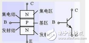
September 12, 2025