\ Cars bring convenience to people's lives, but also bring traffic accidents. Speeding is one of the important hidden dangers of traffic accidents. According to research, most of the image sensors used in road capture systems for speeding vehicles are small area array devices, which are generally 1 million to 2 million pixels, which results in a relatively low number of pixels in the captured image, which can be captured simultaneously. The number is less and so on. Facing this series of problems, image sensors with large area arrays have gradually become the focus of attention. In the design process, the working mode of the MT9P401 CMOS image sensor with 5 million pixels was analyzed, Quartus â…¡ was selected as the development tool, and the driving circuit design scheme was described in hardware using Verilog HDL language. And verification. 1 Introduction of MT9P401 image sensor 2 Circuit design
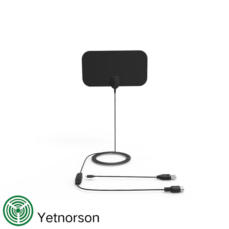
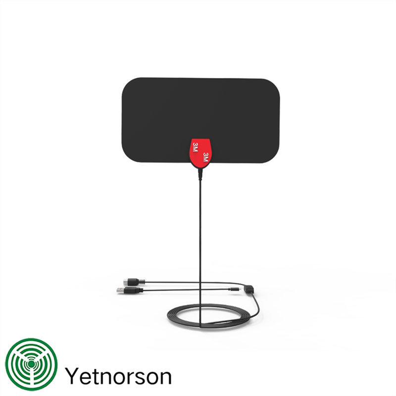
The Description Of Flat Amplified TV Antenna
Innovative flat,razor-thin antenna design.
The Specification Of Flat Amplified TV Antenna
Features
Flat Amplified TV Antenna,TV Antenna With Amplifier,Digital Flat TV Antenna,Flat TV Antenna Shenzhen Yetnorson Technology Co., Ltd. , http://www.yetnorson.com
1.1 Main features MT9P401 is a CMOS image sensor with 5 million pixels from Micron. The main features of the chip are: image resolution of 2 592 H & TImes; 1 944 V, pixel size of 5.7 mm & TImes; 4.28 mm, maximum transmission rate of 96 Mb / s, corresponding sampling rate of 14 f / s, dynamic range 70.1 dB.
MT9P401 image sensor integrates pixel matrix, serial interface, array controller, A / D conversion circuit, etc. When the pixel matrix of MT9P401 is illuminated, the optical signal is converted into an electrical signal due to the photoelectric effect, and the resulting analog signal is transmitted to the internal A / D converter to output the corresponding digital signal. The signals that control the pixel matrix are generated by the matrix controller, which operates through a serial interface.
1.2 Electronic exposure methods The MT9P401 image sensor has two electronic exposure methods, corresponding to two different shutter modes.
(1) Electronic Rolling Shutter (Electronic Rolling Shutter): For any pixel, clear it at the beginning of exposure, and wait for the exposure time to elapse before reading the signal value. Data readout is serial, so clearing, exposure, and readout can only be done sequentially line by line, usually from top to bottom, much like a mechanical focal plane shutter. The characteristic of this exposure method is that the exposure time of each pixel is the same, but the exposure time is different.
(2) Global Shutter (Global Shutter / Snapshot Shutter): A sample-and-hold unit is added to each pixel, the data is sampled within a specified time, and then sequentially read out, so that although the pixels that are read out are still exposed, they are stored The data in the sample and hold unit has not changed. Since the integration time of the image is equal, each pixel is exposed at the same instant. The characteristic of this exposure method is that it can reset all pixels at the same time, but the exposure time is different, and the exposure can be ended at the same time with a mechanical shutter.
1.3 Pixel data readout timing analysis MT9P401 image sensor has a total of 256 internal registers, the internal register settings determine the working state of MT9P401. The communication between MT9P401 and the external controller depends on the I2C bus [1], and outputs each frame of image data under the I2C bus protocol. By default, the pixel clock of the MT9P401 is synchronized with the external input clock. The pixels of a frame of the MT9P401 include 1 944 rows and 2 592 columns. Each pixel clock cycle passes a 12-bit pixel data output through the data output pin The period of the frame valid signal (Frame_Valid) is 70 ms, and the period of the line valid signal (Line_Valid) is 35 μs. When both the frame valid signal (Frame_Valid) and the line valid signal (Line_Valid) are high, pixel data is output. When the frame valid signal (Frame_Valid) is low, vertical blanking occurs. When the line valid signal (Line_Valid) is low, horizontal blanking occurs. The pixel data readout timing is shown in Figure 1. 
2.1 Circuit hardware design The circuit hardware is composed of power module, clock module, CMOS image sensor and FPGA communication module.
(1) The CMOS image sensor part of the power module should provide 5 types of power according to the requirements of the MT9P401 data manual, which are: +1.8 V digital power supply VDD, +2.8 V IO port drive power supply VDDIO, +2.8 V analog power supply VAA , +2.8 V imaging core power supply VDDPIX, +2.8 V phase-locked loop power supply VDDPLL. The FPGA part provides three power supplies according to the requirements of the EP2C8T144C8 data manual, namely +1.2 V digital power supply VDD, +3.3 V IO port drive power supply VDDIO, and +1.2 V analog power supply VAA.
Because the power supply of the CMOS image sensor needs to have higher ripple suppression and noise, and the output voltage drop must be low, combined with factors such as low cost of design and low power consumption, TI's single-ended output LDO is selected in the power supply section [2] (TPS77001, TPS79003) as a power supply module. The working principle of LDO is to adjust the output current through negative feedback to keep the output voltage unchanged. LDO is a step-down DC / DC converter, so Vin> Vout, its working efficiency can be expressed by formula (1): 
The working efficiency of LDO is generally between 60% and 75%, and the quiescent current generated is small.
(2) The clock module clock is the most important and special signal in the entire circuit. The action of each device in the circuit is basically carried out on the transition edge of the clock. This requires a very small delay difference in the system clock signal, otherwise it is easy Causes errors in sequential logic states. Therefore, it is very important to maintain the stability of the clock signal in the circuit design. In this design, the FPGA control clock is provided by an external 50 MHz active crystal oscillator. To prevent the oscillator from interfering with the power supply, add 104 decoupling capacitors next to the active crystal. The external input clock EXTCLK of the CMOS image sensor requires 100 MHz, which is obtained by the PLL [3] frequency multiplication in the FPGA.
(3) The internal registers of the CMOS image sensor and FPGA communication module MT9P401 image sensor determine the working state of the image sensor. After the image sensor is reset, these internal registers need to be configured, so a reasonable external controller needs to be selected for its internal registers Perform related read and write operations. This design uses EP2C8T144C8 produced by Altera as the external controller of MT9P401 image sensor, which has sufficient logic capacity, PLL and I / O quantity. The internal registers of MT9P401 are set through EP2C8T144C8, the configuration mode adopts the serial mode, and the communication protocol adopts the I2C bus transmission protocol, thereby driving the frame valid signal (Frame_Valid) and line valid signal (Line_Valid) of MT9P401.
In addition, considering signal integrity (Signal Integrity, SI), power integrity (Power Integrity, PI) and electromagnetic integrity (ElectromagneTIc Integrity, EMI) in digital system design, try to avoid it in the PCB board routing process Vias, using differential pair design traces, increasing the number of PCB power / ground plane layers, etc., make the overall performance of the design reach an optimal state.
Flat Amplified TV Antenna It has high gain and low error rate Digital TV signal reception,and a significant signal enhancement in actual ues.Increase the reception of TV programs,and eliminate the pause the mosaic images.
Multi-directional design pulls in signals from all directions.
Fast and easy to set up - Unwrap,Plug it in and Scan channels.
IMPORTANT TIP BEFORE YOU BUY:You have to make sure your TV is Digital TV, the local signal is COVERED.You can put it on the wall,on the table or on the window(strongly recommended) and it will make you enjoy watching crystal clear digital & HD shows with many opportunities.
1.Support 1080p.
2.50 miles range.
3.Multi-directional capability.
4.call out all "Free" channels.
5.Connector Type:F Male.
6.V.S.W.R.:<1.5
7.Working Frequency: 174~240MHz,470~862MHz.
8.Gain:25 dBi(with amplifier).
Picture show


June 20, 2020