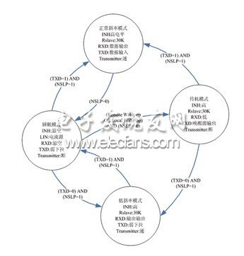
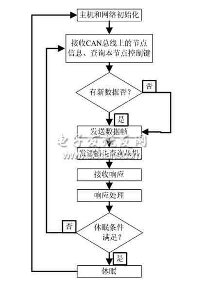
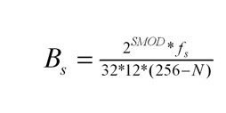
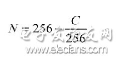
Introduction to LIN bus This article refers to the address: http:// LIN (Local Interconnect Network) is a low-cost serial communication network for implementing distributed electronic system control in automobiles. The goal of LIN is to provide accessibility to existing automotive networks such as the CAN bus, so the LIN bus is an auxiliary bus network. In situations where bandwidth and versatility of the CAN bus are not required, such as the communication between the smart sensor and the brakes, the use of the LIN bus can result in significant cost savings. The LIN specification defines the development tools and application software interfaces in addition to the basic protocols and physical layers. LIN Typical LIN bus applications are joint assembly units in automobiles such as doors, steering wheels, seats, air conditioners, lights, humidity sensors, alternators, and more. For these cost-sensitive units, LIN can make those mechanical components such as smart sensors, brakes or photosensors more widely available. These components can be easily connected to the car network and are easily maintained and serviced. Analog semaphores are typically replaced with digital semaphores in LIN-implemented systems, which optimizes bus performance. Using LIN in the following automotive electronic control systems will achieve very good results: LIN node hardware design 1 LIN interface overall design The LIN node hardware mainly includes the LIN interface circuit part, the control input part, the display circuit or the load drive output, etc., wherein the LIN interface is the core of the node. The LIN interface circuit with Microchip's PIC16F87 as the controller, TJA1020 as the LIN transceiver, and SA57022 as the switching Power Supply is shown in Figure 1. The turn-on and turn-off of the SA57022 power supply output is controlled by the LIN transceiver through the INH pin. Figure 1 Schematic diagram of the LIN interface Because the host node needs to provide a clock reference for the slave nodes in the network, an external crystal oscillator is configured for the PIC16F87 in the host node. In the slave node, the slave node can calibrate its own baud rate by transmitting the sync field in the frame header through the host node, so the external crystal oscillator can be omitted and the RC oscillator built in the PIC16F87 can be used. 2 LIN Transceiver Application Design TJA1020 is a LIN transceiver, which is the interface between the LIN protocol controller and the LIN transmission medium. It is the core device of the node. It is responsible for the waveform adjustment and level conversion of the bus when transmitting and receiving data and the realization of various working modes of the node. The TJA1020 integrates the on-chip slave resistors according to the LIN physical layer specification. In the slave node application, there is no need to externally connect the slave resistors. In the host node application, as shown in Figure 1, between the INH pin and the LIN pin. Serial connection of the host-side resistors and diodes improves the drive capability of the bus and automatically causes the node to go to sleep when the bus is shorted to ground, reducing current consumption. The LIN node constructed with TJA1020 as the transceiver has four working modes: normal, low slope, sleep, and ready to reduce power consumption and electromagnetic radiation. The node state and mode transition in various modes are shown in Figure 2. Figure 2 Node state of the working mode and switching between modes LIN node software design 1 LIN host node software design The LIN host node performs frame processing and communication management functions of the LIN network. The program flow is shown in Figure 3. Figure 3 host program flow The normal communication baud rate of the bus is 9.6k. The slave node always works at this baud rate. When the host node needs to send the synchronous interval field, the baud rate is reduced to 4.8k, and 0x00 is sent, then the 9.6k wave is operated. The slave node of the rate will detect 18 consecutive dominant bits to determine the arrival of a new message frame. The host node restores the baud rate to 9.6k.2 after the synchronization interval field is sent. LIN slave node software design The functions of the LIN slave node can be summarized as two parts: frame header detection and reception and frame processing. In the frame header of each message frame, the host node configuring the crystal oscillator provides a baud rate reference to the slave node through the synchronization field, and the slave node calibrates its own baud rate by measuring the synchronization field to ensure that the message is in the message. Synchronization between nodes in the transmission. The sync field logic value is 0x55, and the waveform is shown in Figure 4. The slave node calculates the calibration self-baud rate by measuring the time interval between the 1st and 5th falling edges in the sync field. Figure 4 Synchronous field waveform Let the serial port of the master node and the slave node work in mode 1 (8-bit UART, variable baud rate), the baud rate of the host node is B, and the slave node measures the sync field 1st and 5th with a timer. The number of counts obtained by the falling edge is C, and the current frequency of the slave node oscillator is fs, and the equation (1) is obtained. Let the slave node counter 1 be operated as a baud rate generator in an 8-bit timer/counter mode in which the constant is automatically reloaded, and the equation (2) is obtained. Synchronize the slave node with the host node, then: Bs=B Formula (4) can be obtained from the formulas (1) to (3). The slave node uses the value of N calculated by equation (4) as the counter 1 to generate a reload value of the baud rate, which can produce a baud rate consistent with the host node. Node production and experiment The LIN node was constructed by using this design to construct the LIN network, and the communication test and preliminary anti-interference test were carried out. Since the message frame header and the message frame response are both sent by the host node, the inter-frame response interval between the message frame header and the message frame response is small. When the LIN slave node transmits instructions or information to each other under the guidance of the LIN host node, the slave network node performs data transmission from the slave node to the slave node. At this time, the LIN host node sends a message frame header, and a LIN slave. The node sends a message frame response and another or several LIN slave nodes receive a message frame response. Since such a message frame transmission requires three or more nodes to participate, a longer interframe space is reserved, so that the transmitting node and the receiving node of the message frame response have sufficient response time to ensure the transmission of the message frame. Successful completion. When the LIN host node requests data from a slave node, the slave bus transmits the data to the host node. At this time, the LIN host node sends the message frame header, and the LIN slave node receives the message frame header and sends it. The message frame responds and the LIN host node receives the message frame response. The electromagnetic environment of the car is bad, so the anti-interference ability of the car communication system is particularly important. The LIN network made according to the design has carried out anti-interference experiments on the BZ-5 type car EDM interference test bench. The network communication is smooth in the test, and various functions normal. Conclusion The CAN/LIN hybrid network in the bus body control system is deeply studied, and the design and implementation of the main control node in the vehicle hybrid network structure is given. In the body control system, the LIN bus is connected to the low-speed body system, and the CAN bus and the LIN bus are built into a hybrid control network through the main control node, so that the control system has the advantages of reliability, high performance and low cost. The use of FREESCALE typical automotive electronic chip and smart contact detection module in the device selection not only realizes reliable network control, but also reduces the development and production cost of the car, and has high practicability. 12V Transformer,Small Transformer,Transformer 24V,Led Transformer Ninghai Yingjiao Electrical Co., Ltd. , https://www.yingjiaoadapter.com
The communication is based on the SCI (UART) data format and uses a single master/multi-slave mode. Use only one 12V signal bus and one node sync clock line with no fixed time reference. This low-cost serial communication model and corresponding development environment have been developed into standards by the LIN Association. The standardization of LIN will reduce costs for automotive manufacturers and suppliers in developing application operating systems. 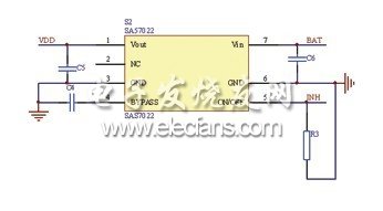
The LIN specification states that the sync interval field is at least 13 consecutive dominant bits (low level). LIN communication is based on the general UART/SCI interface, and byte transfer uses 8N1 encoding, which does not directly produce such a dominant sequence. 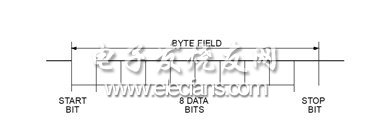

September 03, 2019