Precision Amplifier: Zero Drift Characteristics and Wide Supply Voltage and Input Voltage Range
The op amp is a key component of signal conditioning, which can achieve amplification, buffering, driving, level shifting, active filtering, IV conversion, VI conversion, and various mathematical functions (addition, subtraction, integration, differentiation, multiplication and division, etc.). In different applications, different functional requirements have spawned many different classes of dedicated amplifiers for higher performance and simplified design flow. These high performance devices include instrumentation amplifiers, current sense amplifiers, differential amplifiers, and programmable gain amplifiers.
For precision amplifiers, the two key trends that have steadily advanced over the years and developed rapidly in 2012 are: zero drift characteristics and wider supply voltage and input voltage range. This article will focus on the analysis of these two important technical characteristics and their related Products and applications.
Zero drift amplifier
In many industrial instrumentation and medical applications, the output voltage produced by the sensor is typically low and needs to be conditioned by a signal conditioning circuit with high gain and precision DC performance. However, the op amp's offset voltage, drift, and 1/f noise introduce errors that affect the measurement of DC or low frequency, low level voltages. Therefore, the op amp's offset voltage and drift must be minimized to eliminate 1/f noise for optimal signal conditioning.
Zero-drift amplifiers do a good job of these requirements by dynamically correcting the offset voltage so that the offset voltage is greatly reduced and the noise density is reformed so that the 1/f noise disappears. Zero-drift amplifiers are initially used in systems with an expected design life of more than 10 years, as well as signal chains using high closed-loop gain ("100") and low-frequency ("100 Hz", low-amplitude signals for precision electronic scales, medical instruments, precision Application of metering equipment and infrared/bridge/thermoelectric stack sensor interfaces. In addition, the zero-drift amplifier has a near-zero offset voltage and a higher open-loop gain, a higher power supply rejection ratio, and a common-mode rejection ratio than a standard amplifier.
Several classic zero-drift amplifiers
Zero-drift amplifiers typically use two techniques—auto-zero or chopped—both of which have their own advantages and disadvantages and are suitable for different applications. Self-stabilization adopts the sample-and-hold technique. Because the noise is folded back to the baseband, the in-band voltage noise is large; the chopping uses signal modulation and demodulation technology, which has lower baseband noise, but generates noise spectrum at the chopping frequency and harmonics. . ADI's ADA4528-1 uses a chopping + auto-correction feedback loop technique that greatly reduces the noise spectrum at the chopping frequency and harmonics. The ADA4528-1 is the industry's lowest noise, lowest offset drift precision zero-drift op amp with rail-to-rail input-output swing capability. The ADA4528-1 provides a low offset voltage of up to 2.5μV and the industry's lowest offset voltage drift of up to 0.015μV/?C with an open-loop gain of 140dB, a common-mode rejection ratio of 135 dB, and a power supply rejection ratio of 130 dB. The ADA4528-1 is suitable for instrumentation and medical applications with supply voltages ranging from 2.2V to 5V, such as thermocouples/thermopiles, load cells and bridge sensors, precision instruments, electronic scales, medical instruments and handheld test equipment.
In addition to the use of auto-zero technology in conventional op amps, dedicated amplifier products have also adopted this technology to achieve performance improvements. The AD8230 is a low drift precision instrumentation amplifier with auto-zero technology. The auto-zero feature reduces the offset voltage drift to less than 50 nV/?C and maintains high performance over the extended industrial temperature range of −40°C to +125°C. In addition, the AD8230 has a high common-mode rejection ratio – a minimum of 110dB, which suppresses line noise in measurements that are farther away from the meter; the 16V rail-to-rail common-mode input range can accommodate ground-level variations of several volts. Noise environment. The AD8230's low frequency noise is kept at a minimum of 3 μV peak-to-peak, making it an excellent choice for extremely high DC precision applications.
The AD8217/8/9 are current-sense amplifiers with zero-drift technology that typically have an offset drift of ±100nV/°C over the full operating temperature range of -40°C to +125°C and the common-mode voltage range. The device is also specifically designed to maintain a linear output over the entire input differential voltage range with or without common-mode voltage, while the input offset voltage is typically ±50 μV.
Typical application analysis
The circuit shown in Figure 2 is a precision electronic scale signal conditioning system that uses a low-power buffered 24-bit Σ-Δ ADC AD7791 and two external zero-drift amplifiers, the ADA4528-1. The solution supports single-supply operation and provides high DC gain.
For load cells with a full-scale output of 10mV, this circuit provides 15.3 bits of noise-free code resolution. With this circuit, the custom low-level signal conditioning front end can be designed with great flexibility, and the overall transfer function of the sensor-amplifier-converter combination circuit can be easily optimized by the user. The low-level amplitude signal from the load cell is amplified by two zero-drift amplifiers, the ADA4528-1, which continuously corrects any DC error on its own, keeping it as accurate as possible. In addition to low offset voltage and drift, the ADA4528-1 also has no 1/f noise. This important feature helps the scale to make accurate measurements at DC or low frequencies.
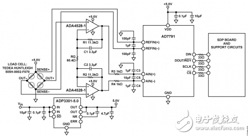
Figure 2: Signal conditioning circuit for precision electronic scales based on ADA4528-1.
The PV Charge Controller works as a voltage regulator, its primary function is to prevent the Battery from being overcharged by the P.V array, being overly discharged by the load, or both.
Controller types:
• Single Stage controllers:
This type of controllers prevents battery overcharging by switching the PV array off when the battery voltage reaches the state of charge set point. The array and battery are automatically reconnected when the battery voltage reaches a lower value called the charge resumption.
• Pulse Width Modulation (PWM) controllers:
PWM controllers are the most common controller on the market today. These charge the battery by rapidly switching the full charging current on and off when the battery reaches a fully charged state. The length of the charging current pulse gradually decreases as battery voltage rises, reducing the average current into the battery.
Solar Street Light Controller,Solar Charger Controller,Programmable Controller,Light Controller
Delight Eco Energy Supplies Co., Ltd. , https://www.cndelight.com