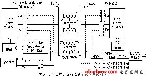
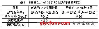
introduction In 1999, power supply via Ethernet cables was no longer a new concept. In June 2003, the IEEE finally approved the 802.3af standard. The standard defines a method that allows DC power to be delivered while transmitting data over Ethernet. It can safely and reliably introduce Power over Ethernet (PoE) technology into existing network infrastructure and is compatible with existing network equipment; it can provide up to 13W of power. This small network device can be powered via an Ethernet connection without the need for a walled AC outlet, which greatly simplifies cabling and reduces the cost of building network infrastructure. In addition, the LAN power supply through the UPS backup can also protect the network equipment from the power failure of the power grid. Like the traditional telephone, it can still operate when the power is off. 1 PoE system composition In a PoE system, a device that supplies power is called a Power Sourcing Equipment (PSE), and a device that uses a power source is called a Powered Device (PD). The PSE is responsible for injecting power into the Ethernet line and implementing power planning and management. Two types of PSE can be used: one is "Endpoint PSE" and the other is "Mid-span PSE". Endpoint PSE is an Ethernet switch, router, hub or other network switching device that supports PoE. The mid-span PSE is a device used to add Power over Ethernet functionality to an existing network. It is designed for power management and is usually placed with the switch. Like the switch, it has multiple I/O RJ-45 ports, corresponding to two RJ-45 jacks per channel, one with a short cable to no Power over Ethernet. A functional network switching device acts as a data input; the other is connected to a remote powered device (PD) that supports 802.3af power supply, acting as a RJ-45 output for data/power dual use. Mid-span devices typically carry power through unused 4/5 and 7/8 line pairs, with the remainder reserved for data transmission. The power supply is injected into the network cable in the chassis without any adjustment of the signal. PDs come in many forms, such as IP phones, network cameras, wireless bridges, cash registers, secure access and monitoring systems. In fact, any device that requires a data connection and can operate at 13W or less can be powered without AC power or battery, and can only get the power from the RJ-45 socket. Figure 1 shows the operation of the PoE system using Mid-span. 2 power supply equipment PSE The PSE is responsible for power management of the PoE system. It continuously monitors the connection status of the PD devices on the network, and according to the power requirements of the PD, delivers the appropriate power to the PD through the Endpoint PSE or Mid-span PSE in the Category 5 cable. Turn off the power when the PD goes offline. Endpoint PSEs support 10BASE-T, 100BASE-TX, and 1000BASE-T networks. The PSE in Endpoint's PoE system can provide a nominal 48V DC power supply between signal pairs or between alternate pairs (but not both). Where the power is transmitted between the pair of signal lines, the 48V power supply is applied to the twisted pair in a common mode by supplying power to the center tap of the coupling transformer, as shown in FIG. 2, having no effect on the differential data signal, and due to the coupling transformer Isolation does not affect the data transceiver. Mid-span PSEs only support 10BASE-T and 100BASE-TX networks, while support for 1000BASE-T networks is not yet defined. The Mid-span PSE provides 48V DC power between the alternate pairs. The Mid-span PSE requires additional cables than the Endpoint PSE, taking up more space and increasing system cost. Before allowing the PSE to power the line, it must check the characteristic resistance with a limited power test source to avoid adding 48V power to the non-PoE-compatible network equipment. Before power-on, the PSE first uses the detection voltage of 2.8V~10V to detect whether there is PD access. In the specific implementation, two voltages (interval of 1V or more) between 2.8V and 10V are sent to the network link, and then the two different current values ​​obtained are calculated (ΔV/ΔI). In order to facilitate PSE identification, IEEE802.3af specifies the performance (characteristics) of the PD during the detection process, as listed in Table 1. Once a valid PD is detected, the PSE needs to know the power consumption of the PD to facilitate system management of the power supply. This process is called PD grading (the IEEE standard stipulates that this process is optional). At this stage, the PSE uses a 15.5V to 20.5V detection voltage to detect the power level of the PD. By absorbing a constant current-graded characteristic signal from the line, the PD indicates to the PSE the maximum power it needs. The PSE measures this current to determine which power level the PD belongs to. The PSE voltage source used during grading must be limited to 100 mA to avoid damaging the failed PD, and its connection time should not exceed 75 ms to control the PD power consumption. Table 2 lists the classification and its constant current characteristics. After successful detection and grading, the PSE can supply power to the PD. During power supply, the PSE also monitors the power supply of each port to provide undervoltage and overcurrent protection. The PSE cannot transmit power to non-PD devices, and the PSE cannot also turn the power on after the PD has been disconnected. Because the power cable may be plugged into a non-PD device or cause a short circuit. The IEEE 802.3af standard specifies two methods for the PSE to detect whether the PD is disconnected, that is, the DC open circuit detection method and the AC open circuit detection method. Different chip suppliers have chosen the most suitable detection method for their system based on the actual situation of the system. The DC breaking method determines whether the PD is online based on the magnitude of the direct current flowing from the PSE to the PD. When the current remains below the threshold IMIN (5mA~10mA) for a given time tDIS (300ms~400ms), the PSE considers that the PD does not exist, thus cutting off the power. The disadvantage of this method is that the PD must periodically draw a certain amount of current from the line to avoid dropping the line when the PD is operating in the low power mode. The AC open circuit method measures the AC impedance of the Ethernet port. When no device is connected to the PSE, the port should be high impedance and may reach several MΩ. When the PD is connected, the impedance of the port will be less than 26.5kΩ; Power, then the impedance is usually lower. The port impedance (ZPORT) is determined by the applied voltage (VAC) and the measured current (IAC), ie ZPORT = VAC / IAC. A number of semiconductor manufacturers have provided PSE controllers that comply with the IEEE802.3af specification. These devices accelerate the widespread adoption of Power over Ethernet while reducing system cost and providing greater reliability. These controllers are Linear's LTC4258/59, Texas Instruments' TPS2383, Israel's PowerDsine's PD64008, Maxim's MAX5922A/B/C, and the upcoming MAX5935. Among them, Linear's LTC4258/59 can manage four-way Ethernet power supply ports, and it can process tasks with order in autonomous operation (without processor intervention). Each mode can be set separately for each channel (automatic , semi-automatic, manual, closed). 3 Powered device PD First, the PD should be able to receive power through the signal line or the alternate line. Usually, the diode is used to “OR†the two power supplies. Because the IEEE specification requires that only one pair can transmit power at the same time; at the same time, the PD should be unpowered. Polarity limits, which can usually be achieved using rectifier bridges or other methods to achieve automatic polarity switching. When the PSE is detected with a voltage between 2.8V and 10V, the PD must have the input characteristics listed in Table 1. The input port of the PD can have an offset voltage of up to 1.9V (to allow the voltage drop of the diode) and an offset current (leakage current) of 10μA. When the PSE is detected with a voltage between 15.5V and 20.5V, the PD needs to absorb a certain constant current to indicate the power it needs to consume (optional), so the PSE can budget the power consumption of the PD and also facilitate the PSE. Management of the power supply. After the detection and classification are completed, the PD will obtain a voltage of 44V~57V from the PSE. At this time, the PD has to comply with several regulations. Before the terminal voltage rises to 30V, it should not consume too much load current to avoid mutual interference with the grading characteristic signal; when the voltage reaches 42V, it must be in full operation. The PD port voltage should be between 36V and 57V in the working state, and the PD should shut down the port when the PD port voltage drops between 30V and 36V. When the PD is working, it cannot continuously consume 350mA current or 12.95W power, and 400mA surge current is allowed in a short time. The input capacitance of the PD must be less than 180μF to keep the inrush current at a reasonable level when the power is turned on. If the input capacitance is greater than 180μF, the PD actively limits the inrush current to less than 400mA. Finally, the PD must maintain a current of at least 10 mA and maintain an AC impedance of 26.25 kΩ or less to avoid dropped wires. In order to make the PD meet the requirements of the IEEE802.3af standard and simplify the design task, several major semiconductor manufacturers have successively introduced the PD interface controller. Available interface controllers are TPS2370/TPS2371/TPS2375 from Texas Instruments, LTC4257/LTC4257-1 from Linear, Max5940A/MAX5940B from Maxim, MAX5941A/B, MAX5942A/B, Supertex The company's HV110K4 and Power IntegraTIons' DPA423G. Among them, Maxim's MAX5941A/B, MAX5942A/B and Power IntegraTIons' DPA423G integrate the PWM controller for DC/DC conversion into the chip. Use them to achieve a very compact and cost-effective PD power supply circuit. Conclusion The IEEE 802.3af standard specifies how routers, switches, and hubs provide power over Ethernet cables to devices such as IP phones, security systems, and wireless LAN access points. As the scale of implementation of PoE gradually expands, a large number of other applications are expected to emerge in the future. It is worth noting that it is expected to push chip suppliers to design chipsets that consume less than 12.95W for notebooks and portable devices. By then, the RJ-45 jack will become a universal power socket, and people will not even remember it in a few years. There have been times when the Ethernet port cannot be powered. PowerDsine even predicts that more than 75% of enterprise network equipment will be powered by Ethernet over the next five years. In the future, PSE power management chips can be integrated into the RJ-45, just as connector suppliers have integrated network isolation transformers into the RJ-45 in recent years. There are also some problems with the Power over Ethernet technology. For example, in the case of a large number of PSE device ports, the power required by the device may be large. At this time, the heat dissipation of the system should be paid enough attention, otherwise the PSE device will be a large heat source. These are all to be resolved in the future. Uvb Lamp,Germicidal Tube Lamp,Uv Sterilizer Light,Germicidal Uv Light Changxing leboom lighting product CO.Ltd. , https://www.leboomuv.com

January 15, 2020