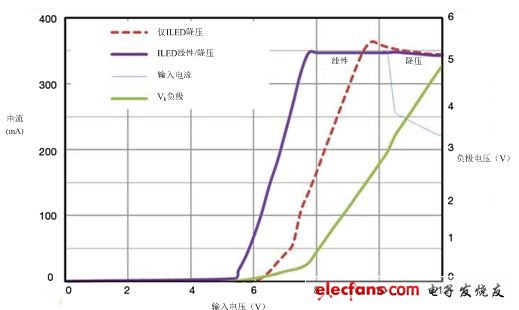
To control brightness, light-emitting diodes (LEDs) require a constant current. This can be achieved by placing a resistor in series with a set of LEDs. Since the voltage and supply voltage of a group of LEDs may change, a dedicated LED driver must be used to ensure current accuracy. The following two solutions are widely used: linear constant current LED drivers and step-up buck switching converters, each with their own advantages and disadvantages. Linear drive is a simple solution with very few components and virtually no noise. However, the amount of heat dissipated and the supply voltage are proportional to the difference between the forward voltages of the LEDs. To prevent overheating, the package may require an additional heat sink on the PCB, which increases the cost and quantity of PCB required, and increases the risk of the driver IC turning off due to thermal shutdown. Figure 1. The LM393 comparator monitors the low-side voltage of the LED string and enables a buck regulator (CAT4201) or a linear regulator (CAT4101). If this drive is placed next to the LED, the extra heat will cause the LED to operate at a higher temperature, reducing its life. Buck (or buck) converters are highly efficient and generate very little heat, but switching solutions require an inductor and a Schottky diode. This solution also produces noise, especially when the supply voltage drops to the LED forward voltage. Radio frequency interference (RFI) is an important consideration in automotive applications. It is recommended to place an EMI/RFI filter in front of the starter converter to prevent the noise generated by the high frequency conversion from returning to the power supply as it may interfere with devices such as AM/FM band radios. Linear converter operation is optimal when the buck converter has poor performance and runs out of margin. In order to avoid the disadvantages and take advantage of the two options, a combination of linear and buck can be adopted to minimize the conversion noise while ensuring efficiency. Ideally, the battery voltage fluctuates widely. For automotive applications (8v to 17v), linear/buck drivers provide the lower noise operating environment and higher efficiency required. When the application voltage rises above the limit, the LED driver switches to buck mode, which prevents the linear driver from overheating. The circuit in this article can individually select an adjustable voltage threshold for each LED driver to switch between switch mode and linear mode with additional hysteresis to ensure smooth transitions. The schematic shown in Figure 1 uses ON Semiconductor's CAT4201 350-mA step-down driver and the CAT4101 1A constant-current LED driver. The logic comparator is also shown. The more common buck structure has a high side switch and a low side diode, which is different for the CAT4201, which interchanges these devices. As with a typical buck switch, when the switch is turned on, the current flowing through the inductor L and the LED increases until it reaches a peak, which is twice the average LED current. Then the switch is turned off. The charged inductor forces the current to continue through Schottky diode D1 and the LED until its value becomes zero. The cycle then begins to repeat. This switched operation is referred to as the critical conduction mode. The R1/R2 resistor divider produces a V+ equivalent to a fraction of the negative voltage. If the comparator (LM393) input voltage is above a fixed reference voltage of 2.5V, the output is high; OUT is low, disables linearity The driver enables the buck converter. If V+ is below the reference voltage, the comparator output is low, enabling the linear driver and disabling the buck converter. The feedback resistor R5 increases the hysteresis of 0.6V, that is, once the negative voltage exceeds 3.6V, the buck converter will start; when the negative voltage drops below 3V, the linear driver will take over. Note that if the other half of the LM393 is not used for other LED power supplies, a better design approach is to ground all unused input and output leads on the LM393. Figure 2 shows the LED current regulation for a single-purpose buck converter and a linear/buck driver. Compared to single-purpose buck converters, linear/buck drivers extend LED current regulation to supply voltages below 8V, which keeps the LEDs lit even if the battery voltage continues to drop. When the supply voltage is lower than 11V, only the buck converter will lose its accuracy and generate more switching ripple current back to the power supply. It is more difficult for EMI filters to suppress ripple current at lower frequencies. On the other hand, linear drives provide a higher regulated and noise-free operating environment over the same supply voltage range. Despite the increased component count, linear/buck joint solutions are valuable for applications that require low noise performance and extended power supply intervals. Linear to buck transition voltage values ​​can be set for optimum thermal performance. Figure 2 Compared to a buck converter only, a linear/buck current sink extends the current regulation range to a lower supply voltage (below 8V) and reduces EMI at low power. Therefore, the LED is in the battery. It can also remain lit when the voltage is low.
Optical coupler is also called optical splitter , is one of the most important passive devices in optical fiber link, is with multiple inputs and multiple output end of the optical fiber connected devices. The fiber optic splitter by the light splitting principle can be divided into the fused biconical taper (FBT type) and planar waveguide type (PLC type).
PLC Splitter, With SC/APC Connector,SC/UPC Connector, LC/APC Connector , LC/UPC Connector
Bwinners Telecom Communication products include: Fiber Optic Splice Closure, FTTH Fiber Optical Distribution Box, FTTH Fiber Optic Socket Face Plate, Fiber Optic Patch Panel Terminal Box, ODF Optical Fiber Distribution Frame, OCC Optical Fiber Cross Connection Cabinets, Network Cabinet, Equipment Enclosure, PLC Splitter, Fiber Optic Patch Cord , Fiber Optic Adapter , Fiber optic pigtail, FTTH Accessories, etc.
Bwinners Equipment Enclosure includes all kinds of Equipment Enclosure, wall mounting enclosure, junction box, network box, electrical enclosure box, stainless steel enclosure, electronic equipment racks, metal cabinets, metal enclosure CATV enclosure, etc.
fiber optic splitter plc, fiber optic cable splitter, optical splitter, Mini Type PLC Splitter, Cassette Type PLC Splitter, Insertion Module PLC Sijee Optical Communication Technology Co.,Ltd , https://www.sijee-optical.com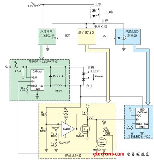


January 21, 2020