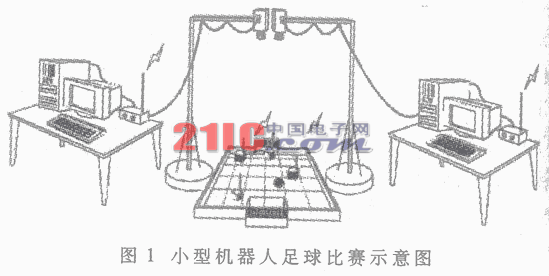
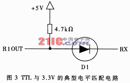
Abstract: This paper introduces the design of a wireless communication system for Robocup F-180 small group soccer robot competition. Including the hardware design and implementation of the sender and receiver systems and their software design. A communication protocol suitable for this system is given, including physical layer coding design, error correction coding design and frame structure design. Football robot is a very challenging and high-tech intensive project, integrating car mechanics, robotics, mechatronics, single-chip microcomputer, data fusion, precision instruments, real-time digital signal processing, image processing and image recognition, knowledge engineering and experts System, decision-making, trajectory planning, self-organization and self-learning theory, multi-agent coordination and wireless communication are all theories and technologies. It is not only a typical intelligent robot system, but also a multi-agent system and multi-robot for research and development. Cooperation and confrontation provide a vivid research model. It provides a standard task to enable researchers to use various technologies to obtain better solutions, thereby effectively promoting the development of various fields. Its listening theory and technology can be applied to industrial production, automated assembly lines, rescue, education and other practical fields, thereby effectively promoting the development of the country's science, technology and economy. Robot football reflects a country's basic research and high-tech development level in the field of information and automation from one side. At present, there are two major series of robot football matches in the world-FIRA and Robocup. The F-180 small soccer robot game used by the system to be discussed in this article is one of the more widely used RoboCup series. The schematic diagram of the F-180 small soccer robot football game is shown in Figure 1. There are 5 robot cars on each side of the game. In terms of hardware equipment, the soccer robot system includes a robot cart, camera device, computer host, and wireless transmission device; functionally, it includes four subsystems: robot cart, vision, decision-making, and wireless communication. 1 System design and implementation The video signal from the camera in the game is processed by the computer to obtain data information for controlling the car, and the wireless communication system is to send these data information to each robot car on the field in a timely and accurate manner. The system uses broadcast methods, each The robot recognizes the useful data sent to itself according to the specific mark, so as to make decisions and actions. The block diagram of the entire system is shown in Figure 2. 1.1 Hardware design of the sending end The sending end mainly uses the PIC16F877 single-chip microcomputer to realize the encoding and control of the transmitter. The computer sends the data through the serial port, and after the PIC16F877 encoding, the data is sent out through the PTR3000 wireless communication module. The TR3000 wireless data transceiver module is a half-duplex transceiver. It uses the NORDIC company's nrf903 wireless transceiver chip. The operating frequency is the internationally-used digital transmission frequency band ISM. The frequency band is 915MHz. The operating frequency can be varied from 902MHz to 928MHz. Using GMSK modulation, strong anti-interference ability, especially suitable for industrial control. High sensitivity, reaching -100dBm, maximum transmit power + 10dBm, working voltage is 2.7V ~ 3.3V. It has a maximum of 169 channels, which can meet the needs of multiple channels, the highest data rate can reach 76.8kbps. Therefore, it can fully meet the needs of data transmission rate and distance of small group robot communication. In this system, PIC16F877 uses a 20MHz clock signal, which can meet the needs of sending and receiving data and encoding in real time. The whole system contains two kinds of power supplies, the power supply of the wireless communication module is 3.3V, and MAX232 needs +5 power supply. The connection of the signal line should also consider the matching of the two levels, and a level conversion circuit should be added where necessary. First of all, the single chip microcomputer should receive the data from the computer. The signal output from the serial port of the computer is converted from 232 level to TTL level through MAX232. However, because the single-chip microcomputer uses a 3.3V level, the signal output by MAX232 needs to be level converted to be input into the single chip microcomputer. The level conversion can use the typical level matching circuit provided by TI (see Figure 3), or 74LVCXX series logic gates. To convert. Because PIC16F877 has only one asynchronous serial port, it is necessary to extend an asynchronous serial port through the 16C550 universal synchronous asynchronous transceiver (USART) chip. This can ensure that the data output from the computer serial port is different from the data rate of wireless communication, so that the original data can be transmitted in time after the communication encoding and packaging data increase, and the received data can be sent back to the computer when necessary. Realize half-duplex channel. The circuit diagram of the system is shown in Figure 4. It can be seen from Figure 4 that the PIC microcontroller uses a parallel port to initialize the 16C550. Since the 16C550 has 10 registers and occupies 8 addresses, the PIC microcontroller uses three general-purpose I / O ports RA0, RA1, and RA2 as address lines to select each register of the 16C550. The single chip microcomputer can continuously detect the TXRDY and RXRDY signals through the RB1 and RB2 pins to know whether the ST16C550 has received data or has already sent data. It is also possible to set the 16C550 as an interrupt mode to generate an interrupt every time a byte of data is received to make the INT signal effective, and the single-chip computer enters the interrupt processing program, thereby making the execution efficiency of the single-chip computer higher. The control of the working state of the communication module mainly includes the signals listed in Table 1, which can be controlled through the ordinary I / O port of the single-chip microcomputer. 1.2 Software design at the sending end When the system resets, the one-chip computer must carry on programming initialization to the register of PTR3000 wireless communication module and 16C550 first. The initial programming of PTR3000 is carried out by synchronous serial signals. There are a total of three signals CFG_CLK, CS and CFG_DATA, which are connected to the microcontroller RC3, RB7, RC5 pins. The PIC16F877 MCU itself has a synchronous serial port function module, but because the synchronous serial data bit of the PTR3000 is 14 bits, not an integer byte, and the 14-bit data must be initialized at one time, it is actually programmed through ordinary I / O It is more convenient to implement these 14-bit synchronous serial signals. The CS signal must always be high during the entire initialization period. See Table 2 for the definition of these 14-bit initialization words. The most significant bit comes first when initializing the synchronous serial signal output. Before programming the PTR3000, its state is the receiving state to avoid wireless interference on other frequencies. After the programming is completed, the state can be changed to the transmitting state. Parameter Next, initialize the 16C550. Since the PIC16F877's own parallel port initializes the 16C550 to set up various registers, it is only necessary to output the address signal of the corresponding byte through RA0 ~ RA2 before outputting each byte. When initializing the settings, set the baud rate of 16C550 to less than 76.8kbps to ensure that the received data can be sent instantly through the PTR3000. 1.3 Hardware design of the receiving end The receiving end is installed on each robot car. Since the robot car is controlled by the DSP controller TMS320LF2407, the PTR3000 wireless communication module at the receiving end is controlled by TMS320LF2407. The data received through the PTR3000 is directly input into the DSP, which is decoded by the DSP to make decisions and send out control signals. Therefore, the receiving end circuit of the wireless communication system is much simpler than the sending end, and only need to use TMS320LF2407 to replace the single chip microcomputer in the sending circuit and connect with the PTR3000 module. The initial programming of the PTR3000 is realized by the ordinary I / O port of 2407, but the PTR3000 remains in the receiving state after the initial programming. 2 Design of the agreement 2.1 Coding design of the physical layer The coding design of the physical layer should be determined according to the characteristics of the physical devices and physical channels used. This system uses the PTR3000 wireless communication module. In order to obtain 0 DC level in the receiving module, the number of logic "0" and logic "1" in the transmitted data must be equal. Only the receiving part that satisfies the above conditions will obtain a high receiving accuracy rate. Idle for a long time will also cause the 0 DC level of the receiving part to drift, because a long time of idleness has always sent a logic "1". Because of these characteristics of the PTR3000, it is natural to think of using Manchester encoding (also known as Digital Biphase or Biphase, Split-phase). It uses a periodic square wave to represent "1" , And its reverse waveform indicates "0". Since the positive and negative periods of the square wave each occupy half, there is no DC component in the signal. In asynchronous serial communication, there is a start bit "0", so the stop bit The length of "1" is also set to one bit, so that there is no DC component in the signal of a total of 10 bits. Only after adding Manchester encoding, the original one byte of data now requires two bytes to be transmitted. 2.2 Error correction coding design In order to ensure that the wireless communication between the main robot and the robot is still stable and reliable under certain external interference, certain anti-interference measures must be taken. This can be achieved by using error correction coding. You can choose error correction coding schemes (14, 8) block code, (7, 4) block code and cyclic code, you need to use a two-byte length to send one byte of effective information; (5, 2) block code and cyclic Code, interleaved code, (21, 8) block code and shortened cyclic code, (21, 9) BCH code, (21, 12) BCH code, need to use the length of three bytes to send one byte of effective information. (7, 4) block codes are used in the system, and good results have been achieved in practice. Its composition is as follows: It is assumed that the original code format without any processing is: The high four-digit supervision code is: The supervision code of the lower four bits is: After encoding, it becomes two bytes in length: The highest bit of each byte is used as a flag bit, which is used to indicate the high four bits and the low four bits. The high four bits are marked with "1" and the low four bits are marked with "0". The receiving end reassembles and decodes through the detection flag. The basic decoding methods include Viterbi decoding and supervised matrix decoding, which can be flexibly selected according to the specific coding scheme. 2.3 Frame format design The general data frame includes the frame header, robot identification, data, data verification, reserved bytes, etc., and is usually arranged in the following format: In order to ensure that the frame can be received accurately, the design of the frame header is crucial. Generally, the frame header needs two or more bytes, and the value and combination with a lower probability of appearing in the data should be selected. In this system, data bytes such as 0xF0 and 0xCC that do not appear in general data can be used as the data frame header. For other types of frames (such as command frames such as kick-off or pause), you can choose to add other words 0x33, 0xC3, 0x3C, 0x0F after 0xF0. This kind of frame header combination does not appear in general data, so it can ensure that the frame synchronization will not go wrong. Each robot on the field recognizes its own data through the robot ID in the data frame. Since there are only 5 robots on the field, the robot ID only occupies one byte. This communication system adopts the PTR3000 wireless communication module for wireless transmission, and uses the codec of the single station to make this system work more stable and reliable, so that the data communication can be timely and correctly transmitted to each robot on the field, fully satisfying the small group The communication rate and correct rate requirements for football robot games. 0-20Kva Diesel Generator,Portable Power Generator,Open Type Power Generator,Container Power Generator Shanghai Kosta Electric Co., Ltd. , https://www.generatorkosta.com
Among them, the wireless communication system is an indispensable link between the host and the bottom robot. It must ensure that the data transmission from the host to the bottom of the robot is reliable, so that the robot can proceed smoothly. Since both sides of the game have multiple robots running on the field at the same time, wireless communication is required to have certain anti-interference. The performance of the wireless communication system directly affects the performance of the robot on the field to a considerable extent. 
The PIC16F877 microcontroller used is an 8-bit microcontroller introduced by Microchip. Using RISC command system and Harvard bus structure, the highest operating clock frequency can reach 20MHz, so the command runs fast. It has a wide operating voltage range and can be used directly with the 3.3V PTR3000 wireless communication module. 
The single chip microcomputer outputs data to the PTR3000 communication module through the built-in asynchronous serial port. Because the nrf903 chip receives and sends data sharing a pin, it needs other circuits to demultiplex. The easiest way is to first connect a 10kΩ isolation resistor to the TX pin of the microcontroller, and then connect it to the DATA pins of RX and PTR3000. But this method has two shortcomings, it will cause the transmitted data to be stringed into the receiving pin of the microcontroller, and the driving ability of the transmitted signal is greatly limited. Therefore, this system uses 74HC244 tri-state buffer as isolation (shown in the dashed box in Figure 4), and the transceiver status is controlled by RB4 of the single-chip microcomputer, so that the transmitted signal and the received signal can not interfere with each other in the half-duplex mode To send.
Table 1 PTR3000 working mode configuration table PTR3000 working mode STBY PWR-DWN TXEN CS Normal work: receiving 0 0 0 0 Normal work: launch 0 0 1 0 Power down mode 0 1 X X Standby mode 1 0 X X
Table 2 PTR3000 initialization control word definition Bit parameter name Symbol Number of bits 0 ~ 1 Frequency band FB Must be for 10 (expressed as the selected frequency band 915 ± 13MHz) 2 2 ~ 9 Frequency CH f = 902.1696 + CH · 0.1536 (MHz) 10 ~ 11 Output Power POUT Transmitting power ≈-8dBm + 6dBm · POUT 2 12 ~ 13 Clock divider output Fup "00" => Fup = fxtal
"01" => Fup = fxtal / 2
"10" => Fup = fxtal / 4
"11" => Fup = fxtal / 8 2
Figure 4
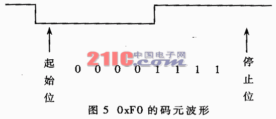
There are some digital sections that will not appear in the data serial port after Manchester encoding, but also have the characteristics of 0 DC component in a byte, and also have a high reception accuracy rate. Such data bytes are: 0xF0, 0x0F, 0xCC, 0x33, etc. From the perspective of the pattern, the timing performance of the 0xF0 pattern is the best (see Figure 5 for its pattern). It is easy to synchronize the asynchronous receiver without errors. Because of this characteristic of 0xF0, it can be used as a synchronization symbol. During the idle time, the communication system always sends synchronization symbols to keep the receiving end synchronized, and it can also maintain the 0 DC level of the receiving module. ![]()
A2 A1 A0 B2 B1 B0 1 X7 X6 X5 X4 A2 A1 A0 0 X3 X2 X1 X0 B2 B1 B0 Frame header Robot logo data Reserved word Data validation 
This small group robot communication system has been applied to the F-180 Robocup small football robot system of the University of Science and Technology of China. In the Robocup small robot football game held in Italy in July 2003, this communication system still showed high reliability in the presence of various communication interferences. In the small group of the F-180 Robocup National Robotics Competition held in Beijing in August 2003, the first team of China University of Science and Technology won the second place in this communication system.
May 28, 2025