Grounding resistance testing is an essential process in electrical safety and system performance. The requirements for grounding resistance are as follows:
a. For AC working ground, the resistance should not exceed 4Ω.
b. For safe working ground, the resistance must also be less than or equal to 4Ω.
c. For DC working ground, the resistance value depends on the specific needs of the computer system.
d. The grounding resistance for lightning protection systems should not exceed 10Ω.
e. In shielded systems, the grounding resistance should not go beyond 1Ω.
The ZC-8 type grounding resistance tester is widely used for measuring the resistance of power systems, electrical equipment, lightning rods, and other grounding devices. It can also measure low-resistance conductors and soil resistivity. This device consists of a hand-cranked generator, current transformer, sliding wire resistor, and galvanometer, all housed in a compact plastic case for easy transport. Accessories include auxiliary probes and cables, which are stored in a dedicated bag.
Before using the tester, make sure all components are present:
1. One ZC-8 grounding resistance tester.
2. Two auxiliary grounding rods.
3. Cables of 5m, 20m, and 40m in length.
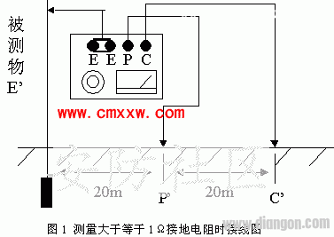
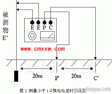
When measuring grounding resistance, connect the E terminal to the 5m cable, the P terminal to the 20m cable, and the C terminal to the 40m cable. The other ends of the cables should be connected to the grounding electrode (E’), potential probe (P’), and current probe (C’) of the object being tested. Ensure that E’, P’, and C’ are aligned in a straight line with a distance of 20 meters between them.
For measurements above 1Ω, refer to Figure 1 for the wiring setup. Connect the two E terminals on the meter together.
Mirror Dash Cam Front And Rear Mirror Dash Cam Front And Rear,Touch Screen Dash Cam,Dual Dash Cam Mirror,Rear View Mirror Dash Cam SHENZHEN ROSOTO TECHNOLOGY CO., LTD. , https://www.rdtkdashcam.com When measuring resistance below 1Ω, use the wiring diagram shown in Figure 2. Connect both E-terminal wires directly to the grounding body to eliminate errors caused by wire resistance.
Operation steps:
1. Ensure all connections are correct.
2. Make sure the instrument is firmly connected to the grounding electrode, potential probe, and current probe.
3. Place the meter horizontally and adjust the galvanometer to zero.
4. Set the “magnification switch†to the highest level, then gradually increase the crank speed to 150 rpm. If the galvanometer pointer moves, adjust the dial to bring it back to “0.†The measured resistance is the dial reading multiplied by the magnification factor.
5. If the dial reads less than 1 and the pointer is unbalanced, switch to a lower magnification setting until balance is achieved.
6. If the galvanometer pointer shows instability, try adjusting the crank speed to stabilize it.
Safety precautions:
1. Do not perform measurements during thunderstorms or when the object is energized.
2. Handle the instrument carefully during transportation and use.

July 14, 2025