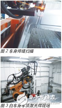
At present, the body-in-white welding line of foreign automobile companies generally adopts robotic welding lines with high degree of automation and flexibility, mainly including resistance spot welding and laser welding. A very large limitation of laser welding in the welding production line is that it has high requirements on the positioning accuracy of the body parts. If the deviation is too large, it directly affects the welding quality, and even cannot be welded at all. This problem is difficult to solve in domestic auto factories, because the body is assembled from hundreds of parts, and the error of the final body is also amplified several times, which is difficult to meet the accuracy requirements of laser welding. In order to solve the problem of weld seam accuracy when implementing the laser welding of the body-in-white roof robot, Huagong Farley successfully introduced the 3D vision system into the roof laser welding production line and achieved good results. The application of 3D vision system in white body roof laser welding is the first in the same industry in China, and has accumulated valuable experience for the promotion of this technology. The 3D laser vision system is a high-tech based on computer, information processing, 3D image processing and laser. The system is a good method to reduce tool cost and improve production efficiency. After using visual technology, the weld seam can be pre-processed before welding, and the robot track adjustment can be used to compensate for the lack of precision of the vehicle body and greatly improve production efficiency. Here, this article will focus on the application of the 3D laser vision system and its debugging steps in the application of the body-in-white laser welding production line. First, the system consists of The 3D vision system is mainly composed of the following parts. It communicates with the robot controller through the ETHERNET IP protocol. The connection method is shown in the figure below. Component Description: 1 Robot control cabinet for robot control and communication and control with sensors; 2 3D vision system controller, control of 3D vision system and communication with external devices; 3 robot body, realize the robot body operation and the installation and fixation of the sensor; 4 three-dimensional vision sensor, weld photo and image processing; 5PC, parameter setting and status monitoring of the sensor; 6 power supply cable, sensor power supply; 7 Ethernet cable for communication with the 3D vision system; 8 robot standard connection cable, the robot controller is connected to the body. Second, the working principle The working principle of the 3D vision system is that the robot performs laser photographing of the weld by controlling the laser three-dimensional vision system mounted on the sixth axis before welding. The three-dimensional vision system processes the image by the image processing technology to identify the geometric coordinates of the weld position. The coordinate value is transmitted to the robot controller through the bus, and the robot controller compares the coordinate with the standard coordinate to calculate the position deviation, and then automatically corrects the welding trajectory according to the error. Third, the implementation method The first step is to identify the weld. After the sensor is connected to the robot and communicates normally, the sensor must first identify the weld, that is, according to the weld form, set the sensor parameters, then open the laser for testing, the sensor will perform laser shooting, and after image processing, and then The preset weld form is compared, and the parameters are adjusted by the parameters and the robot position until the sensor can obtain a stable weld. The second step is sensor calibration. The sensor correctly recognizes that the weld is still not working properly, because the sensor is mounted on the robot, it has nothing to do with the robot, and the sensor calibration is to determine the relative relationship between the sensor and the robot, so that the position of the weld identified by the sensor can be use. The third step is weld seam scanning and correction. To achieve weld correction during welding, first determine a standard body, that is, move the robot to the appropriate scanning position on the weld, control the sensor to scan the weld, and save the weld position as a standard position. Before the welding, the robot is moved to the same scanning position for scanning, the identified weld position is compared with the previous standard weld position to obtain a deviation, and then the trajectory is corrected, which can realize the points on the trajectory at X Corrected in the Y, Z direction. Conclusion The application of the Jianghuai M111 project has successfully achieved mass production of the whole vehicle. According to the application situation of the site for more than one year, the application of the three-dimensional vision system greatly reduces the requirements of laser welding on the accuracy of the vehicle body, and realizes batch automatic production and stable operation. Reliable, this provides a good solution for the promotion and application of laser welding in the automotive industry. The application of 3D laser vision system is beneficial to reduce project and operating costs, improve production efficiency, product quality and production flexibility, train and train relevant engineering personnel, and at the same time effectively promote the progress of white body production technology, and improve the competition of Chinese automobiles. Force has a positive effect on building an innovative country and enhancing China's overall national strength. Weatherproof/Waterproof Type F Outlets "Waterproof Type F Outlets Black,Waterproof Type F Outlets,Waterproof Outlet Plug,Waterproof Exterior Outlet " Yang Guang Auli Electronic Appliances Co., Ltd. , https://www.ygpowerstrips.com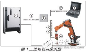
April 25, 2024