How to test PAM4 signal
With the growing demand for big data, the bandwidth requirements of core networks have significantly increased each year. As a result, transmission technologies must continue to evolve to meet these market needs. Currently, the main approaches to further enhance bandwidth include increasing signal rates, expanding the number of transmission links, and boosting the amount of information transmitted within the same time window—essentially carrying more data per symbol. One such method is PAM4 (Pulse Amplitude Modulation), which increases data density by using four distinct signal levels instead of the traditional two used in NRZ (Non-Return-to-Zero) coding.
This article introduces the fundamental concepts of PAM4 and explores how to test PAM4 signals effectively.
**First, NRZ and PAM4 Signals**
Figure 1 below illustrates the eye diagrams of both NRZ and PAM4 patterns. While NRZ uses two signal levels, PAM4 employs four, allowing it to carry twice the amount of data per symbol. In other words, one symbol in NRZ represents one bit, whereas one symbol in PAM4 represents two bits. This makes PAM4 a promising technology for higher data rates.
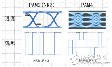
*Figure 1: NRZ pattern and PAM4 pattern*
**Second, Applications of PAM4 in High-Speed Ethernet and Coherent Optical Communication**
1. **High-Speed Ethernet**
The Ethernet 802.3bj standard supports 100Gb/s over backplane and copper cabling, using either NRZ or PAM4 modulation. Since copper has limited bandwidth, NRZ struggles to achieve high data rates. PAM4, however, can transmit two bits per symbol, doubling the data throughput at the same rate. However, its sensitivity to noise is a major challenge.
2. **Baseband Modulation in Coherent Optical Communication**
In coherent optical communication systems, such as 100GbE, QPSK (Quadrature Phase Shift Keying) is commonly used. This technique modulates both the in-phase (I) and quadrature (Q) components of the optical carrier, enabling efficient data transmission. Figure 2 shows the basic block diagram of a 100G DPQPSK coherent system.
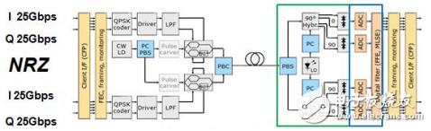
*Figure 2: Basic block diagram of 100G DPQPSK coherent optical communication*
QPSK uses four phase states (45°, 135°, 225°, 315°) to represent two-bit symbols. Each symbol corresponds to one of the four combinations (00, 01, 10, 11). This allows for efficient use of the channel, transmitting two bits per symbol.
Figure 3 illustrates how phase information maps to encoded data and the corresponding constellation diagram.
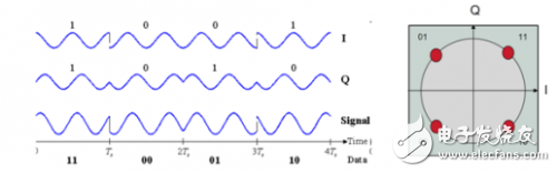
*Figure 3: QPSK modulated signal transmission and constellation*
When PAM4 is applied, it doubles the data capacity compared to NRZ. This enables a transition from 100GbE to 200GbE. Additionally, PAM4 serves as the baseband for 16QAM (Quadrature Amplitude Modulation), where I and Q channels each transmit 4-level PAM4 signals, resulting in 16 possible combinations. The constellation diagram in Figure 4 shows this structure.
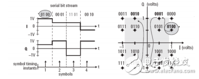
*Figure 4: Transmission and constellation diagram of 16QAM modulated signal*
Finally, Figure 5 demonstrates a coherent optical communication system based on PAM4.
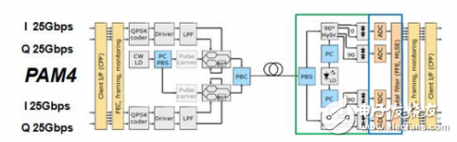
*Figure 5: Coherent optical communication transmission system based on PAM4*
**Third, PAM4 Test Solutions**
Teledyne LeCroy offers a comprehensive test solution for PAM4 signals, integrated with high-bandwidth oscilloscopes for detailed analysis. The package includes features such as clock recovery, eye diagram analysis, jitter and noise measurement, level testing, and more. It also supports simulations and BER (Bit Error Rate) prediction.
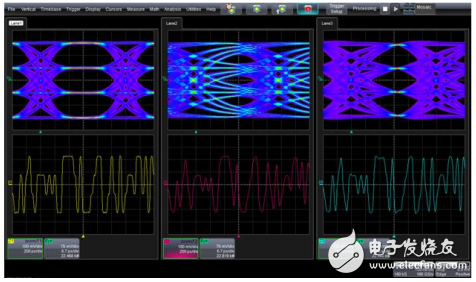
*Figure 6: Multi-link PAM4 signal eye diagram test*
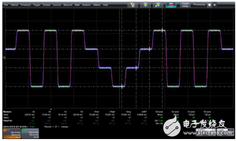
*Figure 7: PAM4 signal level test*
Rf Coaxial Connector,Female Smb Coaxial Connector,Mcx Coaxial Cable Connector,Mcx Coaxial Connector
Changzhou Kingsun New Energy Technology Co., Ltd. , https://www.aioconn.com