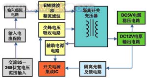
Usually, there are two sets of household fixed-frequency air conditioner controller power supplies, one set is 12 volts and the current is less than 600 mAh; the other set is 5 volts obtained by 12 volts through 7805 voltage regulation, the current is less than 200 mA, the controller power supply The total power is generally within 10 watts. At present, most of the power supply of the household air conditioner controller is still diode-rectified using a low-frequency iron core transformer, and the capacitor is directly filtered to output a 12-volt power supply. Since the 12 volt supply is not regulated, the output voltage value will change as the input mains voltage increases or decreases. The line voltage of the relay that is indispensable in the air conditioner controller is provided by the 12 volt power supply. Therefore, when the mains voltage is too low, the 12 volt voltage is too low, which causes the relay to be unreliable and affects. The reliability of air conditioning. When the mains voltage is too high, the voltage of 12 volts will be too high, which will lead to a large increase in the heat loss of the relay line, which will accelerate the aging of the relay, which is also a factor that cannot affect the service life of the air conditioner. Many of the control functions of the air conditioner controller are done by relays. It is impossible to save these relays. This makes the air conditioner manufacturer have to choose a relay with a wide operating voltage range and high price. Since the air conditioner controller uses the low-frequency transformer linear power supply to have many of the above-mentioned safety hazards and shortcomings, the low-frequency linear power supply scheme is a low-cost solution on the surface, but from the perspective of the cost of the air conditioner and the maintenance cost, The linear power supply cost is not necessarily low, so that the profit of the air conditioner manufacturer cannot be improved. Because of this, the low-frequency transformer linear power supply is no longer used in foreign air-conditioning controllers, and is replaced by an efficient, energy-saving, stable and reliable switching power supply that overcomes the shortcomings of such low-frequency linear power supplies. Its principle block diagram is shown in Figure 1. Figure 1: Block diagram of switching power supply According to the market requirements, ON Semiconductor has introduced the NCP101X series of single-chip switching power supply ICs with simple circuit, isolation, high efficiency and energy saving. It is specially designed to replace the low-power linear power supply used in household appliances and industrial fields. The NCP1014 is especially suitable for designing switching power supplies for home air conditioning controllers. Performance characteristics of NCP1014 single-chip switching power supply The NCP1014 single-chip switching power supply IC can meet the design of switching power supply for household air conditioner controller with AC 85-265 volt wide voltage input range and output power within 10W. This switching power supply can not only replace the existing bulky linear power transformer, but also It can also increase various protection functions of the controller power supply to improve the reliability of the air conditioner. The NCP1014 also has the following performance characteristics: 1) An isolated, energy-saving switching power supply can be constructed with a minimum number of peripheral components. Compared with the traditional low-frequency linear power solution, it not only achieves better voltage regulation and load regulation than the low-frequency linear power supply, but also improves the conversion efficiency of the entire power supply. 2) Dynamic self-powered technology is adopted. When the power supply is less than 5W, the auxiliary power supply winding can be omitted, simplifying the design of the power supply high-frequency switching transformer. The use of frequency jitter technology minimizes electromagnetic interference and reduces the device and power consumption of the EMI filter. 3) Built-in 700 volt high-voltage MOS power switch tube, can be applied to switching power supply with AC voltage input range of 85 ~ 265 volts. According to requirements, the power supply can be designed to work in continuous (CCM) and discontinuous (DCM) modes. . 4) Ultra low power consumption. If the IC is powered by an external bias circuit, the switching power supply can operate without noise in the low-peak current frequency hopping mode at no load, and the power consumption of the whole machine is less than 100 mW. 5) Current mode controls the peak current of the power switch tube in each switching cycle, so that the switching power supply has a good dynamic load response speed. The IC internally has a soft start circuit of 1 millisecond at the same time, which ensures that the switching power supply has no internal current when it is turned on. , voltage overshoot phenomenon. The fixed operating frequency is available in 65kHz, 100kHz, and 130kHz. Flexible switching capacitors can be selected according to the size of the power supply. 6) The protection function is perfect. The feedback optocoupler can be directly connected to the IC feedback pin without the need for complicated peripheral circuitry. The chip has a protection circuit that automatically restarts after short circuit, open loop fault detection and overvoltage lock protection circuit, current limiting protection circuit and overheat protection circuit with hysteresis characteristics. Typical application scheme of NCP1014 air conditioner controller switching power supply ■The basic structure of the circuit The 10 watt isolated air conditioner controller switching power supply consisting of NCP1014 uses a common flyback topology, as shown in Figure 2. FR1 is the fuse resistor, D1-4 is the input stage rectifier, C1 and C2 are the input stage filter capacitors, and L1 is the input stage EMI differential mode suppression inductor. D5, C3 and R1 are absorption circuit ultrafast recovery diodes, high voltage ceramic capacitors and power resistors, respectively. T1 is an EE22 ferrite core high frequency power switching transformer. U1 is the NCP1014 monolithic switching power supply IC, and D6, R2 and C4 are auxiliary power rectifier diodes, current limiting resistors and electrolytic filter capacitors, respectively. U2, R3 and ZD1 are secondary voltage feedback high voltage isolation optocouplers, current limiting resistors and voltage reference Zener diodes, respectively. D7 and C6 are 12 volt output power ultrafast recovery rectifier diodes and electrolytic filter capacitors, respectively. U3 and C7 are 5 volt output power regulator ICs and electrolytic filter capacitors, respectively. C5 is a safety Y2 capacitor. Figure 2: Common flyback topology circuit structure ■Circuit design points Taking Figure 2 as an example, the basic points of designing the switching power supply circuit of the air conditioner controller with NCP1014 are introduced. ◠High frequency power switching transformer T1 The high frequency switching transformer is one of the core components of the switching power supply, and its parameter design directly affects many performances of the switching power supply. All aspects of the switching power supply must be comprehensively considered during design. When the discontinuous mode is used, the inductance of the switching transformer should be selected less. Conversely, when the continuous mode is used, the inductance of the transformer should be selected to be larger. The choice of transformer turns ratio should be considered in conjunction with the required maximum duty cycle, reverse switching voltage of the power switching transistor and the secondary rectifier diode. In general, switching power supplies with low power use a discontinuous mode of operation. ◠Primary input filter capacitors C1 and C2 C1 and C2 can be used with ordinary electrolytic capacitors. The main function is to smooth the input voltage and filter out the 100 Hz ripple voltage to provide a relatively stable DC voltage for the switching power supply. For wide voltage input range, C1 and C2 must at least ensure that the switching power supply has more than 2 microfarads per watt. ◠Differential mode suppression inductor L1 L1 and the input capacitors C1 and C2 together form a 滤波-type filter circuit, which acts to suppress the EMI of the switching power supply. It is recommended that L1 use an inductor with a ferrite core. The inductance of L1 should be greater than or equal to the design value, and the RMS current can withstand a certain margin. ◠Primary RCD absorption circuits R1, C3 and D5 Its main function is to absorb the rising edge voltage energy generated when the power switch tube is turned off, reduce the peak voltage amplitude, and prevent the power switch tube from over-voltage breakdown. R1 requires a power resistor of 1W or more, and the resistance is about 68 kiloohms. C3 requires a ceramic capacitor with a low equivalent series resistance, a capacity of about 1000 picofarads, and a withstand voltage of 400 volts or more. D5 requires ultra-fast recovery diodes with a reverse voltage rating of 600 volts or more. ◠Auxiliary power circuits R2, C4 and D6 C4 uses 22 microfarad ordinary electrolytic capacitors. D6 requires a switching diode with a sufficiently high reverse withstand voltage. Since the protection functions of overload, overvoltage and overcurrent of NCP1014 are realized by detecting the voltage amplitude of auxiliary power supply, special attention should be paid to R2 resistance adjustment. The resistance value is too large, IC is easy to undervoltage protection, and vice versa. Pressure protection. ◠Secondary output filter capacitor C6 The main role of C6 is smoothing filtering. Since the equivalent series resistance (ESR) and capacity of C6 directly determine the ripple voltage of the output voltage, it is necessary to select an electrolytic capacitor with a low ESR value and a large capacity. ◠Feedback sampling circuits U2, R3 and ZD1 U2 uses a common isolation optocoupler, such as PC817. The Zener ZD1 provides a reference voltage of 12 volts output voltage, and R3 is the current limiting resistor of the Zener diode ZD1, limiting the operating current of the Zener diode to 5-10 mA. It is also possible to fine tune the voltage of 12 volts by adjusting the value of R3. D7 should use an ultrafast recovery diode with a sufficiently high reverse withstand voltage. To reduce the forward conduction loss, a Schottky diode with a sufficiently high reverse withstand voltage can also be used. In discontinuous mode, the reverse recovery time of D7 should be less than 75ns. When using continuous mode, the reverse recovery time of D7 is required to be less than 35ns. MUR220 belongs to this type of ultrafast recovery diode. Do not use a normal fast recovery diode because the reverse recovery time of this tube is several hundred ns. ◠Secondary 5 volt linear regulator circuit U3 and C7 U3 uses a low-cost TO220 package 7805 regulator IC, because the 5 volt supply current is less, the U3 input can be directly connected to the 12 volt power supply. C7 can meet the requirements by using 47 microfarad ordinary electrolytic capacitors. Conclusion: &nbs
Another noteworthy problem is that this low-frequency linear power supply has low conversion efficiency, large static loss current, no recoverable overload, over-temperature, short-circuit protection, etc., and many safety hazards. 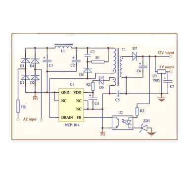
â— Secondary rectifier diode D7
p; Household air conditioning controller power supply switching power supply scheme is the ultimate trend of air conditioning product development. The NCP1014 single-chip switching power supply solution has the advantages of stable and reliable performance, flexible use, simple circuit, low cost, etc., and has a considerable application market in the household air conditioner control power supply. If necessary, the NCP1014 can also be used to design a multi-output switching power supply. The main point is that the total output power of the power supply is equal to the sum of the output power of each channel.
:
introduction
1 time
Window._bd_share_config = { "common": { "bdSnsKey": {}, "bdText": "", "bdMini": "2", "bdMiniList": false, "bdPic": "", "bdStyle": " 0", "bdSize": "24" }, "share": {}, "image": { "viewList": ["qzone", "tsina", "tqq", "renren", "weixin"], "viewText": "Share to:", "viewSize": "16" }, "selectShare": { "bdContainerClass": null, "bdSelectMiniList": ["qzone", "tsina", "tqq", "renren" , "weixin"] } }; with (document) 0[(getElementsByTagName('head')[0] || body).appendChild(createElement('script')).src = 'http://bdimg.share. Baidu.com/static/api/js/share.js?v=89860593.js?cdnversion=' + ~(-new Date() / 36e5)];
September 19, 2018